Build yourself a simple inline lightbulb test circuit.
Here's an example.
Current limiting with a Dim Bulb Tester.
If you are going to stay with this, I would recommend buying a variac as well. Both have saved me a few times.
Here's an example.
Current limiting with a Dim Bulb Tester.
If you are going to stay with this, I would recommend buying a variac as well. Both have saved me a few times.
Ah well. It's a learning curve. Experience is expensive. I had one the other night with a cap the wrong way round. It didn't explode but very hot. Current limited bench supplies saved that fate.
1) Does look like reverse polarity.
2) What voltage rating were your caps.
All you can do is put down to inexperience and move on. Double check everything.
1) Does look like reverse polarity.
2) What voltage rating were your caps.
All you can do is put down to inexperience and move on. Double check everything.
Another trick I learned from Professor Leach is to put 100R 1/4 watt resistors in series with the power leads. If it powers up without smoking the resistors you can remove them. If something is wrong the resistors will limit the current before they burn up. Saved a Leach amp channel when I soldered the color coded power supply leads the wrong way around.
This won't work with high bias amps, but if chip amps and most amp front ends draw very little current.
This won't work with high bias amps, but if chip amps and most amp front ends draw very little current.
Check and double-check critical wiring. Always check the PSU rails BEFORE connecting it to the amp!
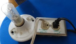
When I made my light bulb tester, I used double plug and a light socket. One outlet is in series with the light bulb and the other outlet is hooked up parallel to the bulb. The series side is used for powering up an amp and the other is used to drain capacitors. It gets used every day and it cost me less than $10.
Attachments
Alright guys, I'm back again. Sorry for the long wait. I finally resoldered the entire thing. This time I made sure I got everything right, I read the datasheet of the amp to make sure it made sense with the layout, and double checked the design of the power supply.
So I turned it on again, this time no explosions. So after ~30s I turned it off again, and connected the multimeter to the speaker outlets and turned it on again.
I had it on for ~15s, all that time the multimeter read -8.8V DC. I had nothing else connected to the amp, no input, no output.
-9V DC is much too high right? what is wrong? There's a piece about matching R2 with RF. I tried to do that but my multimeter isn't very precise. How close would they need to be?
Do you have another multimeter?
Matching by buying the same value 1% resistor should be enough to be well under 100 mV.
Is your input shorted to ground or floating? Double check your input and feedback connections. A floater could result in high DC.
Is this an LM3886 that requires a 10K resistor to the negative rail to turn on? Could you have connected that to the negative input instead/too? On the LM3886 the inverting input is pin 9 and you connect pin 8 to the negative rail via 10K or so...
Double check power rails.
What are the voltages at pins 8 (V In -) and 7 (V In +)?
Have you taped up the multimeter probes? I would tape all but the very tip. Can help save accidental shorts.
What are the voltages at pins 8 (V In -) and 7 (V In +)?
Have you taped up the multimeter probes? I would tape all but the very tip. Can help save accidental shorts.
BobEllis: The resistors come from the same strip of gold band resistors. Should I get ones with better tolerance?
There's no 10K resistors in my circuit, so I don't think so. The whole circuit is just 4 resistors.
I had not shorted the input to ground, I turned it on again with the input wires shorted, and the DC dropped to -6V. So still too high..
mcd99uk: alright, I'll measure that. My girlfriend is afraid of the explosions so I'll have to wait before she goes somewhere else 😛
mcd99uk: alright, I'll measure that. My girlfriend is afraid of the explosions so I'll have to wait before she goes somewhere else 😛
He he 😀
Measuring these two voltages should indicate where to look for the problem.
Edit: Yours is an LM3875 (according to your pic). There isn't an enable pin.
Safety glasses...
You must be using an LM3875 then. Double check that the resistor from the negative input ins connected to ground and the negative rail pin doesn't connect to it.
You must be using an LM3875 then. Double check that the resistor from the negative input ins connected to ground and the negative rail pin doesn't connect to it.
Okey weird, the Vin- is like -31, but the Vin+ is around -10.. are they both supposed to be negative? why is the Vin+ not 30 as well?
It's like the cliffhanger of a thriller series 😛 Good night guys!
@BobEllis: Sorry yeah, I'm using the LM3875 🙂
It's like the cliffhanger of a thriller series 😛 Good night guys!
@BobEllis: Sorry yeah, I'm using the LM3875 🙂
Last edited:
Both inputs should be ~0V. With power OFF what is the resistance from each input to ground? It sounds like you connected the feedback loop to the negative rail.
Got my safety glasses! So I'm trying to measure the resistance from Vin- and Vin+ to ground, and I get very mixed results, I think I'm just doing it wrong, but if I put the multimeter to 2K and measure then it starts at some low resistance like 0.5, and then slowly climbs up to 2 and then displays the 'higher than 2k' value 1.
Does that sound weird?
I double checked the Vin+ btw, I think I hadn't screwed it tightly enough the previous time, now I measured 31V at both rails.
I don't measure any short circuits between any points on the board from any of the inputs.
Could the 6V dc be just from the resistors with too much tolerance?
Measuring resistance with a capacitor in parallel will give an initial low resistance, due to current flowing into the capacitor.
As the capacitor charges up to the meter's "testing voltage" the current flow lowers. This lowering of current is indicated as an increasing resistance. Eventually the charging current becomes lower than what would flow into that maximum resistance (1999r) and the meter indicates "1" = >1999r
If there were an actual resistor of less than 1999r then the meter would asymtotically approach that resistor value. Try it. solder a 1k resistor across the terminals of a 100uF cap. Measure the resistance?
Swap the leads around. Measure again.
Learn what your instruments are telling you.
Thanks AndrewT, I realise I was testing the capacitors now.
I disconnected the power supply, and now I've blown two fuses trying to test it. Maybe I short circuited something when I resoldered the wires, or something is really wrong with it.
Before I measured 0V on one of the power inputs, and ~21V on the other, so I assumed the power supply had a defect so I disconnected it. But now it blows fuses so I'm not sure what to do now..
What? The sequence of events is becoming confusing. Post#134 has the rail voltages correct at (presumably) +/-31V. You disconnected the supply from the amplifier because you say you later had (apparently) )0V, 21V. If the PSU circuit is still complete and it is functioning, what do its output voltages (ground to rails) measure now?
It seemed on reading, that even after getting the connections of the supply correct and the correct output voltages that the supply is damaged. Are you having difficulty understanding what schematics or assembly diagrams are showing you, or is this a handling problem where things are shorting everywhere with the power still on as you handle them?
Either way, you need to look at some guidelines as suggested before and go about things systematically to make sure that when something "works" it does work and stays that way without doubt. Maybe some connections are being affected as you make other changes or domestic cleaning is happening.
I think it was predictable for your first DIY, what would result with point to point wiring. This is a skill as much as technical talent in following diagrams and apart from in nice, big vacuum tube designs, is a minefield of potential shorts until you are familiar with the techniques and best wiring sequence to get safe connections. For some guys it's natural. I get frustrated with it, to be honest.
Always opt for PCBs until you are really confident with what makes circuits work and then experiment with the unknown. It will make assembly of modules as simple as Lego building if you follow pics better than schematics. Have you read or at least looked at the illustrations and articles on this site? The security of connections is paramount for the operation and safety of electronic circuits so make certain of your soldering skills and the proper tinning of wires to ensure that wires, blobs of solder etc. are not just being held tegether by resting on each other.
If you'd rather just get things going, make sure the power supply section is producing the correct outputs again and if not, whether diodes are shorted, or possibly open circuit. Read the polarity of caps again and verify the correct connections because simple power supplies are just that, simple. When you have it right, turn to the power amplifier and use a PCB this time to eliminate stoogeing around with doubtful wiring and connection quality.
You could continue to fight with this and succeed too but maybe you'd rather not take more risks than you need to. Good fortune 🙂
I'm sorry if I've been a bit too foolhardy with this. I just really like the idea of point to point soldering, but I obviously have made it harder for myself than it should have been. I soldered a power supply for my DAC that had roughly the same amount of parts as this so I thought it would work out.
Anyway, it seems I've royally screwed this up and broke the most expensive part.
Since you've said the sequence had become a little confusing, these are the steps I've done since the beginning of the project:
I first soldered the power supply circuitry. Then I tested it, and it seemed to work, giving the expected voltages on both outputs.
Then I soldered the amp circuitry. Foolishly, I connected it to the power supply to test it, but I had no fuses or protection in place. I had soldered the caps in reverse, and they exploded, along with the chip.
I started the amp circuitry over, this time reading the circuit very well and making sure I sort of understood what everything was for. I also bought safety glasses and a mains socket with integrated fuse holder, along with fuses. I connected it and this time nothing exploded, but there was a big DC voltage across the output leads of the amp.
Someone suggested that this could be because the input voltages were unbalanced. Measurements I did seemed to suggest something was going wrong with the input power as well.
I disconnected the power supply, and tried to test it, but the fuse blew.
That brings us to today, I disconnected the power supply from the transformer, and still the fuse blows. It's a 2A slow blowing fuse, but it still blows immediately.
Does this mean the transformer is absolutely broken? Are these things repairable?
Last edited:
The transformer is likely OK. It takes time to "cook" a transformer.
By the nature of transformer constructions, you can't easily repair them.
By now, you may realise that if a transformer is just 2 or 3 windings (as toroidal transformers usually are) a low resistance measurment of the windings will show whether it is OK. You can be more certain by powering it up without connections to the secondary windings and measure the AC voltage across each secondary winding. Next, connect the diode bridge and recheck that you have +/- DC rail voltages with respect to the transformer secondary Centre Tap or common ground. Bear in mind that small diodes or diode bridges can can act like a fuse, since they will blow at higher than specified current. Then add the electrolytics in their correct alignment with the positive terminals to the more positive connection. Check that you now have steady and more correct rail voltages. It should be obvious too, that this is just a simple, logical sequence of checks.
I assume you have identified the windings correctly and determined the "sense" or direction of the windings to ensure the total output from the transformer adds to twice the voltage of each winding and doesn't null it to zero, if you get this wrong. Also, be sure to read the beginners guide and all guides to simple power supplies on the ESP site, as I linked above.
Without experience, it's likely you'll blow more fuses and they can be more expensive than resistors, which I would use, wired across the fuseholder, since a 100R, 1/2W resitor can limit the current and prevent all damage, which a fuse must burn out to achieve and you can't then determine the problem, which current limiting can. By measuring the voltage across both resistors, Ohm's law tells you the current and this is the preferred method of measuring current with DMMs - don't use the meter's current ranges as it is far too easy to damage your meter, leads and get false results.
Normally, we use a "bulb tester" - a DIY assembly of an incandescent lamp of around 60W, wired in line with the mains active lead. It's simple in principle but must be a very safe assembly to ensure that it protects you or others in the home from injury, if you leave it lying around for some reason. I'm sure you're aware of the potential for fatal injury when exposed to even brief contact with 220V mains potential.
This gizmo also limits current in the whole device and indicates excessive current by glowing brightly - up to it's normal brightness in the case of a direct short circuit. Normally, a chip amp will draw little current after the initial surge of charging the caps etc. and there should be no glow or just a glimmer, showing it is working OK. The power supply alone, should not show any glow.
Thanks Ian. I've definitely read the guides you linked me, I think it was after the first explosions I saw the light of respecting safety 🙂
My next step is definitely going to be building the bulb tester. Regular lightbulbs have been outlawed here, but I think there's still some sorts that are still legal. A power saving lightbulb would probably be too slow / low wattage right?
So about the transformer, what you are saying is that it's normal for the transformer to blow a fuse when the secondary wires are not connected? If so could my next step be to have both a fuse and a 100R, 1/2W resistor in series with the transformer so it won't blow the fuse?
Thanks for being patient with me, your sequence of checks was my plan exactly, I got worried because of the fuses blowing.
- Status
- Not open for further replies.
- Home
- Amplifiers
- Solid State
- How do I find out which amp I should build?