I'm not struggling with how to wire it up 🙂 I'm following the AudioSector design exactly, as I've stated a few times. The designer has stated that this design can be done point to point, so that's what I'm doing..
Do you think doing it this way may result in a poorer quality amp?
Do you think doing it this way may result in a poorer quality amp?
You should be ok point to point. I did my leach amp supply hard wired. These days I prefer to have a nice PCB though. The end result looks more professional. I have bought some nice ones from Jims Audio (Ebay) for not a lot of money in the past.
It's just easier to avoid making mistakes on a pcb. I did a 3 way crossover with lots of EQ and phase adjustment point to point.
Good luck, have fun.
Good luck, have fun.
Amptech, thank you for your troubleshooting assistance along with all the others like you who were here when I joined. I think a lot of Terry's problems are self inflicted, as he doesn't seem to follow a methodical approach to troubleshooting (same as 8 years ago). When he first discovered that the issue was protection circuit related, I would have replaced reheated the solder joints and replaced the transistors for 10 cents. As you read there, I might also have just pulled them and left it unprotected. A sound basis in basic amp theory would be helpful.
Wow, not sure why I feel the need to defend myself. I have been accused of "filtering" the suggestions I have received and not following a methodical approach to trouble shooting. The "filter" I use is ignorance. You nailed it with your last sentence. I don't have a sound basis in basic amp theory. I thought I made that perfectly clear when I asked for help. When guys suggestion includes terms like VAS, long tailed pair. protection circuit, etc. a grey fog passes through my brain. If someone says, Q10 or R36 of D7, I know just where to look.
For the record, if you read through the thread about my amp, you will see that I did in fact reflow all the solder as well as replace all of the transistors, some more than once. The Leach amp is a sound design and a very good sounding amp. I wouldn't hesitate to suggest it to someone who is new to the hobby. I have learned a lot from it, especially with this last go around. I started a thread thinking others might learn something from it. Perhaps all that was accomplished was to show my ignorance. I should maybe ask the mods to delete it so no more people are scared off from building one.
Blessings, Terry
Terry,
I am sorry I offended you. That was not the intent.
My main purpose with that comment was to show a different approach to troubleshooting than that encouraged by those who were trying to help. They were tweaking the protection circuit design, when it was obviously not functioning as designed. Advanced troubleshooting when its purpose was beyond your experience or what was likely needed in the circumstances. It is a proven design and board. Lots of amps have been built on that board design and worked well. Why tweak values instead of looking for something like a solder bridge or incomplete etch? It is hard to be methodical when you have more experienced people pulling you different directions.
I live in a world of regulatory compliance where if you didn't document it, it didn't happen even if it was something as automatic as breathing. From your comments in your thread it appears that you may not be documenting all your steps. And I did miss that you'd replaced those parts early on, but there apparently was another issue that was resolved with "scratching around" although you didn't document all the steps you'd taken until the summary.
Again, sorry I offended you.
Last edited:
Hi Bob, no problem.
It was a tough journey getting that amp fixed. Believe me, I tried my best to document everything I did each day. My hopes when posting up schematics with voltages attached was that someone who understands circuits could look at them and say "this voltage is wrong, look here, or disconnect this". Truth is, I learn very little if all I do is stuff components in a board, fire it up and play music. I learn a ton more from searching out and solving problems. I have learned more in the last month than in the entire time I have been in DIY audio.
I must say, I would probably suggest the Low TIM over the Superamp. There is almost no difference between my Low TIM and Superamp in sound or power. My Low TIM is built from Jen's boards and has 3 pair of plastic outputs side though so that might have some baring on that.
Blessings, Terry
Your perseverance in the face of adversity is admirable, Terry. I hope that all beginners reading this thread and yours will learn from it. There's a lot of knowledge on this board, freely shared. The forum members will get you through the problems if you stick with it.
Hey guys, my trouble begins! 😛
I had a busy week, but now I have time again! I've just now began on making the first amplifier channel, and am testing the rectifier circuits.
So I connected the transformer to the rectifiers, and turned the power on. Nothing went boom, carefully I held my hand above the circuit to feel if anything was becoming hot, but nothing was so I proceeded to test the output voltages.
One rectifier circuit said 32V, the other said 0V. So I probably messed up the second one somehow, I'm going to look at it carefully, measure all connections and see if I got something wrong.
Does it make a difference when I accidentily reverse the transformer leads? Maybe I wired it up wrong? I'm going to check and test that 🙂
check polarity of diodes. That's the most likely thing.
What dimensions are your caps and how many do you have per rail?
What dimensions are your caps and how many do you have per rail?
Ah I'm so relieved, I found the mistake 🙂 That's what I get for not using a preprinted PCB 😉 hopefully this means there's no broken diode 🙂
I have the rectifier circuit built as on page 5 here: http://www.audiosector.com/nigc_kit-users_guide.pdf so with just a small 10uF capacitor on each rail.
Waiting for my soldering iron to heat up now..
I have the rectifier circuit built as on page 5 here: http://www.audiosector.com/nigc_kit-users_guide.pdf so with just a small 10uF capacitor on each rail.
Waiting for my soldering iron to heat up now..
Haha 😀 It works! they both say 31,9V now 🙂 tomorrow I'll solder the first channel and see if we can get some sound through this baby 😛
So tomorrow was a bit later 😛 I've got the first channel all done now, and I'm going to test it. First thing I want to do is measure how much DC voltage is on the output, that's important right? When I do this, should I have a heatsink attached to the chip? Will it become too hot very fast, even when there's nothing connected to it?
I'm asking because I don't have an easy heatsink for it that it can be attached to while I work on it. If it's necessary that it's cooled all the time I'll have to think up some jig to be able to work on it without removing the heatsink 🙂
I'm asking because I don't have an easy heatsink for it that it can be attached to while I work on it. If it's necessary that it's cooled all the time I'll have to think up some jig to be able to work on it without removing the heatsink 🙂
You should always have you output devices on a heat sink when you test them. That goes for chip amps, too. Some chips have built in protection circuits that will prevent thermal damage but they will disappoint as the protection kicks in.
Once you get it on a heatsink and double check your power connections you can power up and check for DC offset. Then feed it a signal, measure the output. It should be amplified. Try it on with a speaker that you don't care about or are rugged and listen for clean sound. That's all there is to testing a chip amp. If it passes those tests you're ready to give it a good listen.
Once you get it on a heatsink and double check your power connections you can power up and check for DC offset. Then feed it a signal, measure the output. It should be amplified. Try it on with a speaker that you don't care about or are rugged and listen for clean sound. That's all there is to testing a chip amp. If it passes those tests you're ready to give it a good listen.
Holy **** guys, this thing did not want to be turned on! It, exploded! and then I stupidly disconnected the wrong power cable, and the capacitors both exploded too! I don't know what I did wrong yet. The chip exploded the second I turned it on. I double checked I did all my wiring right yesterday night, but perhaps I had a bad joint or an accidental short-circuit, maybe a component in reverse..
Enjoy the pictures:
Enjoy the pictures:
Attachments
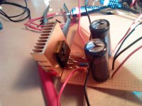
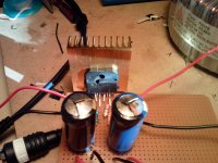
That's what it looks like with your caps exploded like that. Wasn't that a wonderful smell? Welcome to the club!  Most if not all of us have been there.
I now triple check polarities before I connect anything.
I hope that heat sink was for testing purposes. If your speakers drop much below 8 ohms you'll want more heat sink than that to prevent the SPiKE protection from kicking in. When it does it sounds nasty.
Most if not all of us have been there. I now triple check polarities before I connect anything.
I hope that heat sink was for testing purposes. If your speakers drop much below 8 ohms you'll want more heat sink than that to prevent the SPiKE protection from kicking in. When it does it sounds nasty.
Last edited:
- Status
- Not open for further replies.
- Home
- Amplifiers
- Solid State
- How do I find out which amp I should build?