I presume that your multimeter doesn't have a continuity / diode function? You can get multimeters with that function for not a lot of money I've seen them for 10 Euro or less. Otherwise you could put a resistor in series with the diode and connect to a power source (eg bench PSU / batteries) then measure voltage drop across it.
Read up about light bulb testers. Do not power up a PSU for the first time without one.
Yes once wired up you can measure the voltage between +ve, 0V and -ve, 0V. yes, should be constant voltage.
Diodes are quite tough. All depends on what temp your soldering iron is at and how long you had the heat on for. Components are designed to withstand a certain amount of heat for mass production regimes.
I am initially building a single channel exactly the way Peter Daniels prescribes, so with the small cap and then the single 1500uF cap without a snubber.
If it passes the lightbulb test, the test driver test and then manages to drive a cheap speaker with accurate sound, I am going to put some more research in, I think just putting 10,000uF worth of 1500uF caps per channel without changing anything else at all is the plan.
Just out of curiosity, my friend who also dabbles in electro a bit wondered why audio amplifiers still use transformers and not the modern switched psu's. I haven't seen any mention of those in any audio guide I've seen so far, but he says they should be able to pull off audio currents and are much cheaper than transformers.
Sensible way to go... Experimentation and research is the name of the game.
You could get away with less capacitance. There is a point where adding more parallel caps doesn't improve anything. But this is DIY and the beauty of it is that you can do what you want, no matter how over the top it is. 🙂
As far as SMPSs go I don't see a problem with using them in audio. The only reservation I have is that the noise generated needs to be dealt with properly. Need to make sure that the power rail filtering is up to the job and that any electromagnetic fields are shielded properly.
Having said that I would only use an SMPS with a Class D amp. Otherwise I'd stick with the transformer. Maybe I'm just stuck in the past.
....Maybe also cautious about the galvanic isolation of some SMPS. They aren't exactly encouraged for DIY discussion by the forum rules either..... Maybe I'm just stuck in the past.
....Maybe also cautious about the galvanic isolation of some SMPS. They aren't exactly encouraged for DIY discussion by the forum rules either.
True.
And not to upset the mods I will end my discussions on SMPS here. I'm sure all that needs / could be said has been said before in other threads.
Anyway, its far more satisfying having a big chunk of iron / copper with some beefy components hung off it. 🙂
True.
....
Anyway, its far more satisfying having a big chunk of iron / copper with some beefy components hung off it. 🙂
Why is it that we equate weight with quality in so many things? Things that feel heavy for their size feel better made.
As mentioned even if the isolation issues are dealt with, RFI shielding is not for the faint of heart or inexperienced. It can cause all sorts of problems. Big iron and capacitors do the job, take little special skill to assemble properly and satisfy the density = quality rule. To me, the idea of buying modules and putting them into a case doesn't do much to satisfy the DIY itch. If I were to design and build a SMPS, it would lead to likely failure. Most novices would likely meet the same fate, so it makes sense to go with a linear supply.
As with many things size / weight counts. For, example, what engine would you choose 2.0 Turbo or 3.2 V6? Both have similar outputs. I know some from other parts of the world would view a 3.2 as a starter motor.
I once built an SMPS (NOT MAINS) 12V DC to +/-60V DC. It operated ok. Massive peaking on the output and it transmitted very effectively at 90Khz. Never used it for its intended purpose. In fact never used it again after testing. It was for a car amplifier. Didn't trust the input filter with the car electronics for a start.
Agreed, module plugging doesn't satisfy either.
Last edited:
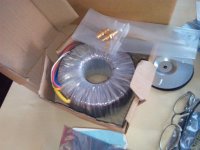
I just received my transformer, it's bloody huge! I was expecting it to be less than half this size! 😀 Heavy too.
I now have all ingredients, looking forward to soldering it up when I'm done with work 😀
I now have all ingredients, looking forward to soldering it up when I'm done with work 😀
I just received my transformer, it's bloody huge! I was expecting it to be less than half this size! 😀 Heavy too.
The satisfaction... 😉
Enjoy the smell of smoking rosin, Tinco. Pictures...
Give me a 3 liter straight six with a roundel. 😉
...2.0 Turbo or 3.2 V6?
Give me a 3 liter straight six with a roundel. 😉
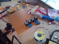
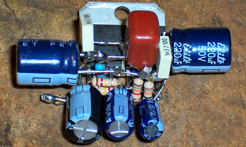
Here's some pictures, I just finished soldering the rectifier part. I also included a picture of my messy workbench and of the transformer with an rca plug for scale 😉
Attachments


Let's call it - Hybrid soldering; Using Point-2-Point technique with a solder tab perf board! 🙄What do you mean by hard-wired? I think this is called point to point soldering.
I feel so hip now 😀 Is this unusual? I thought most people did it this way, using the perf board for stability, and then making the connections using wire.
It's not ideal though, I often need a third hand to hold the wire that I need to solder still.
You guys made me think about it, and I've thought up a way that might make it simpler without using a perfboard pcb.
Step 1: layout the entire circuit in wire out of one piece of wire (as much as you can) by pretending all components are just wire. Solder joints where necessary.
Step 2: solder the components to the wire (even though they are all short-circuited by the wire).
Step 3: clip all the shortcircuits!
Is that an idea? does anyone do this? 😛
That may be a legitimate way to do it on a perf board, but most PCB don't always approach a circuit linearly like you would logically think of doing - or at least it doesn't always look linear. PCB layout is a black art I think! 🙂 I've used the push in perf boards for prototyping simple circuits where you simply plug, unplug components with ease, but never for permanent circuits. I'm a big fan of professionally done PCBs for projects I don't want to spend hours trouble-shooting when things don't work. Just my preference though. Point-to-point works fine on many simple circuits. Hey, that's the way it was always done before PCBs! 😀 I remember my first Heathkit O-scope....I feel so hip now 😀 Is this unusual? I thought most people did it this way, using the perf board for stability, and then making the connections using wire.
It's not ideal though, I often need a third hand to hold the wire that I need to solder still.
You guys made me think about it, and I've thought up a way that might make it simpler without using a perfboard pcb.
Step 1: layout the entire circuit in wire out of one piece of wire (as much as you can) by pretending all components are just wire. Solder joints where necessary.
Step 2: solder the components to the wire (even though they are all short-circuited by the wire).
Step 3: clip all the shortcircuits!
Is that an idea? does anyone do this? 😛
Have a look at this point-to-point.
Have fun.
- Status
- Not open for further replies.
- Home
- Amplifiers
- Solid State
- How do I find out which amp I should build?