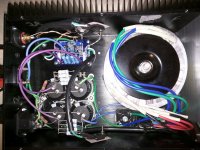
I can't for the life of me figure out what I did wrong with the power supplies in these mono F5s. I'm bringing it up on variac. With the rectifiers not connected to anything, the DC voltage looks good. However, with the rectifiers connected to the caps, what is, say +/- 5V with the rectifiers not attached to anything becomes just over 0V, whether or not the PS is hooked to the signal board. It is like I have shorts in the PS. I have stared and stared and stared at it.
I know the chassis are small and it is tough to see the wiring. Thoughts? Before law school, point to point tube amps were no problem. Now I'm an idiot.
Paul
I know the chassis are small and it is tough to see the wiring. Thoughts? Before law school, point to point tube amps were no problem. Now I'm an idiot.
Paul
Attachments
Not sure what you are asking but the rectifiers need the caps after them to smooth the DC, measuring DC at the rectifier w/no caps is not a reliable way to measure DC output. You need the caps there to smooth the DC.
What is your transformer voltage and what is the voltage across the last set of caps?
What is your transformer voltage and what is the voltage across the last set of caps?
With the rectifiers not connected to anything, the DC voltage looks good. However, with the rectifiers connected to the caps, what is, say +/- 5V with the rectifiers not attached to anything becomes just over 0V, whether or not the PS is hooked to the signal board. It is like I have shorts in the PS.
Are the capacitors connected with the right polarity?
They are. You can see the stripes in the pics.
Do the rectifier blocks' positive terminals (with notches) go to the capacitors' positive terminals,
for both of the supply circuits?
you might get 0V between V+ and V- when you connect blue and green to get GND 0V, if this happen, try to connect blue to another green
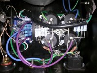
Are the rectifiers wired correctly? I only see one and coming off of it to the caps are both plus and minus. If there is another rectifier block, one for each secondary then it should be minus and each rectifier block should only feed one polarity. If you are using the dual secondaries as a center tap you might be correct. It's hard to tell in the pic.
There's a good diagram here (scroll down). The chokes are resistors in your psu, of course.
http://forum.zelfbouwaudio.nl/viewtopic.php?f=7&t=15498&start=125
There's a good diagram here (scroll down). The chokes are resistors in your psu, of course.
http://forum.zelfbouwaudio.nl/viewtopic.php?f=7&t=15498&start=125
Last edited:
Also, running the mosfets off the board is a good way to smoke the amp. The gate and source resistors need to be as close as possible to the mosfet pins to prevent oscillation. You could probably jumper the boards and mount the resistors on the pins. Don't find out the hard way, your speakers won't like 24v DC on the voice coils.
Since these are monos you probably have enough heatsink to crank the bias. I've gone up to 2 amps on a single pair of mosfets. Run as much bias as the chassis lets you...the f5 loves bias.
Since these are monos you probably have enough heatsink to crank the bias. I've gone up to 2 amps on a single pair of mosfets. Run as much bias as the chassis lets you...the f5 loves bias.
It looks like you've got one green and one blue to each rectifier.
I guess the blue ones should go to one and the Green ones to the other rectifier.
Figge.
I guess the blue ones should go to one and the Green ones to the other rectifier.
Figge.
It would also be a good idea that if you must use similar colours for different parts of the circuit, pick up some 'texta colour' pens and/or add labels - it's very easy to make a mistake over and over again without clear labels/colours on the wiring, especially the floating gnd and chassis gnd wires
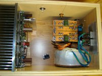
I would seriously suggest either get an insulated boot for the IEC mains socket or some big dia heatshrink - asking for trouble with all that mains jumble - I assume there's a power switch and fuse hidden away somewhere ?
I would seriously suggest either get an insulated boot for the IEC mains socket or some big dia heatshrink - asking for trouble with all that mains jumble - I assume there's a power switch and fuse hidden away somewhere ?
Sorry for being blunt but your wiring is a big mess and might pose a safety hazard. You won't want to get electrocuted.
I would suggest you take a look at some of the builds in the pictures thread and see what members are doing regarding safety measures.
Use a terminal block with crimp connectors or at least heat shrink over every 230AC solder joint. Your secondaries are wired incorrectly. The 2 blue wires should go into a diode bridge and the 2 green ones into the other one.
You don't need a power switch if you plan to leave these on all the time, but a fuse is certainly a must have, for your own protection.
Your secondaries are wired incorrectly. The 2 blue wires should go into a diode bridge and the 2 green ones into the other one.
This may be incorrect. The antek transformers use a green blue pair for each secondary.
Yes a fuse is mandatory.
Attachments
This may be incorrect. The antek transformers use a green blue pair for each secondary.
Yes a fuse is mandatory.
Indeed!! I wrote before checking the datasheet. It doesn't make much sense IMO though, as you can easily wire them wrong.
You appear to have two thermistors attached to one heatsink leaving one mosfet not monitored.
Thermistors normally should touch the mosfets to prevent thermal runaway.
The magic smoke is just waiting to get out there!
Thermistors normally should touch the mosfets to prevent thermal runaway.
The magic smoke is just waiting to get out there!
This may be incorrect. The antek transformers use a green blue pair for each secondary.
Yes a fuse is mandatory.
Yes, and those "pairs" are not random, use a multimeter set to continuity to determine which green goes with which blue. (again, if using Antek with green-blue pairs.)
Russellc
A Variac does not help. What did the bulb show?Post #1 - OP's uses a variac .....
The transformer secondaries are wired correctly, with the right pairs. As I said, the voltages look good from the rectifiers when they are not connected to the caps.
There are two rectifiers--one is tough to see. (And it is impossible to see the soft start thermistor wiring that is between them--it is all under the transformer leads). Each rectifier is wired like the one you can see: with a blue coming off of the positive of the rectifier and a green off the negative. That is why you see the blue to the positive rail and a green to the negative rail, each from different bridges. The corresponding green and blue are tucked back to the ground between the caps.
Regarding all the comments about things that are not my current problem:
The AC is fused, of course. The fuse is in the IEC block. Yes, some heatshrink on the IEC terminals would be nice, but I didn't do it. It is not 230v, of course.
Yes, the mosfet gate resistors are soldered directly to the mosfets with the appropriate bridges on the pcb, even though NP says that it should be just fine with leads this long on the mosfets and the gates on the board.
I know it would be better if the thermistors actually corresponded to the mosfets and were closer to the mosfets. But some folks don't use the thermistors at all. We had this discussion about these particular amps many months ago. In the alternative, I'm not crazy about sending yet more wires across the entire chassis. To see whether the thing will run at a stable temp, I need to be able to turn them on!
Regarding power switches: I wish folks wouldn't leave class A amps on 24/7. Owning class A amps is bad enough for my conscience regarding my carbon footprint. Leaving them on is not an option for me. And it sure wouldn't help with the heat problem these are destined to have.
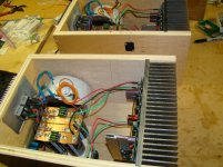
And finally, yeah, the wiring is a mess and nothing really fits. These chassis are too small. I bought these chassis and many of the parts from a forum member here who gave me a good deal because he wanted to see some F5 monoblocks. I don't think they really fit. They are not particularly safe when wired this tight, and contrary to one of the posts above, I don't think the heatsinks are quite big enough. I suspect they will run pretty darn hot. But to see how hot they'll be, I need to be able to fire them up to begin with.
Paul
There are two rectifiers--one is tough to see. (And it is impossible to see the soft start thermistor wiring that is between them--it is all under the transformer leads). Each rectifier is wired like the one you can see: with a blue coming off of the positive of the rectifier and a green off the negative. That is why you see the blue to the positive rail and a green to the negative rail, each from different bridges. The corresponding green and blue are tucked back to the ground between the caps.
Regarding all the comments about things that are not my current problem:
The AC is fused, of course. The fuse is in the IEC block. Yes, some heatshrink on the IEC terminals would be nice, but I didn't do it. It is not 230v, of course.
Yes, the mosfet gate resistors are soldered directly to the mosfets with the appropriate bridges on the pcb, even though NP says that it should be just fine with leads this long on the mosfets and the gates on the board.
I know it would be better if the thermistors actually corresponded to the mosfets and were closer to the mosfets. But some folks don't use the thermistors at all. We had this discussion about these particular amps many months ago. In the alternative, I'm not crazy about sending yet more wires across the entire chassis. To see whether the thing will run at a stable temp, I need to be able to turn them on!
Regarding power switches: I wish folks wouldn't leave class A amps on 24/7. Owning class A amps is bad enough for my conscience regarding my carbon footprint. Leaving them on is not an option for me. And it sure wouldn't help with the heat problem these are destined to have.
And finally, yeah, the wiring is a mess and nothing really fits. These chassis are too small. I bought these chassis and many of the parts from a forum member here who gave me a good deal because he wanted to see some F5 monoblocks. I don't think they really fit. They are not particularly safe when wired this tight, and contrary to one of the posts above, I don't think the heatsinks are quite big enough. I suspect they will run pretty darn hot. But to see how hot they'll be, I need to be able to fire them up to begin with.
Paul
- Status
- Not open for further replies.
- Home
- Amplifiers
- Pass Labs
- How did I goof up these F5s?