Hi!
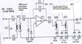
I need help from the forum. Attached is the pic of a portion from a Delta Modulator card for speech applications (speech transmission over 1-bit). You can see the input is lablled as 300-3400 Hz , -3.5dBr/600 ohm. It means the input signal is expected to be in this range.
The input signal is received by a coupling transformer (V42231-s78-A from siemens in RM5 core , 5 pin former, faraday shield, ref# 605). The signal is then amplified by an Op-Amp.
What comes next is a bit confusing for me(606 and 607)...I guess this is a Low pass LC filter, but i cant guess of what kind (T, L or PI). This is made by feeding the op-Amp output to a coil wound on a former (with RM5 core again, Only one side of former pins are used 1,2,6) so it seems to me a "Centre Tap inductor" with 2 pin as common. Both 606 and 607 have similar construction but differ in some parameters (like DC resistance between 1-2, 6-2 and 1-6 pins and so too the inductance).
There are Styroflex caps shown below the coils (574-578). These are of extremely hi precision. Like 8.25n 1%, 7n 1/2.5%. These are very hard to find.
My question is :
1) If I replace 8.25nF 1% with 8.2 nF 5%, and 7n 1/2.5% with 6.8 nF 5%...how would it effect the filter response? Currently the filter is cutting at nearly 3.5Khz.
2) What if I replace two 7n, 1% parallel caps with a 14nF cap? Is it admissible?
Please Advice