As above: is there any possibility to adapt OBH-8 circuit to MC cartridges? Any comments is welcome.
Ludwik
Ludwik
I assume this phono amp is MM only?
If so, there's no real way to 'convert' it to MC, as these MC-buggers need much more voltage gain (with the exception of high-output MCs, but in that case a MM-stage is already perfectly suited).
Of course you could use an input transformer.
Have fun, Hannes
If so, there's no real way to 'convert' it to MC, as these MC-buggers need much more voltage gain (with the exception of high-output MCs, but in that case a MM-stage is already perfectly suited).
Of course you could use an input transformer.
Have fun, Hannes
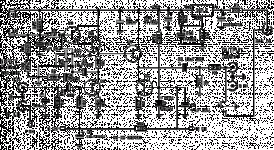
Here is OBH-8 circuit diagram. Any comments?
Yes... Can You upload in a better resolution 🙂 I'm about to get one myself, and would like to see if there are any chance of improving it.
Best regards
Ebbe
Exactly this topology also used by the Cambridge Audio phono modul for the integrated amp "Atac 3" and the "A3i". It sounds very fine. Because this modul uses a SRPP, you must add for moving coil cartridges with low output (200-400uV) a MC head line amp (gain approx. 10 times). I recommend a used JC-1 from Mark Levinson,OK, I try.
http://www.zenn.com.sg/ML_JC1.JPG
for MC cartridges >500uV output voltage (medium- and high output) gain factor of your OBH-1 must be enough. Perhaps a lower value of input termination resistor you must choice (mostly arround 1-2 kohms).
From the low cost MM RIAA preamplifiers this is one of the best sounded, that I know.
Last edited:
As Alex Nikitin said, it is possible to raise voltage up to 40V and changing R13 to 1Watt. It will double the output voltage and gives ~70dB gain.
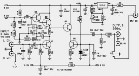
There is another edition of OBH-8 - special edition with jfet.
http://obh-8se.narod.ru/obh8SE_S.jpg
The developer of this RIAA head amp from Creek with interesting descriptions is to find there:
http://www.diyaudio.com/forums/soli...dge-audio-a3i-repairs-mods-7.html#post1987331
Enhancing Capacitors for RIAA Network (1000 times, uF instead nF)
For bigger capacitor values in the RIAA network I have to increase significantly the idle current through the SRPP stage.
How I can realize this?
Genuine schema you will find about post #5+7.
And another question: why is the emitter current through Q2 not defined by a resistance, rather depends on the Hfe of Q3 ??
Last edited:
hi,
I assume that the only way to satisfyingly accommodate for MC pickups with this stage would be to use a dedicated lownoise MC-Prepre or stepup transformer.
In all sims of amplification stages with this or similar topology, noise was an issue.
Noise figures may be good enough for MM-pickups but not for MC-pickups.
A drawback of this otherwise clever and elegant circuit.
jauu
Calvin
hi,
I assume that the only way to satisfyingly accommodate for MC pickups with this stage would be to use a dedicated lownoise MC-Prepre or stepup transformer.
In all sims of amplification stages with this or similar topology, noise was an issue.
Noise figures may be good enough for MM-pickups but not for MC-pickups.
A drawback of this otherwise clever and elegant circuit.
jauu
Calvin
Some while ago I've published the "2010" version of this circuit - specially for DIY.
Simple Phono Stage 2010
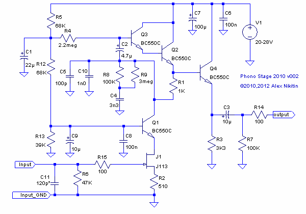
That version can work with either MM or MC cartridge. For a medium-output MC cartridge (~0.4-0.7mV@1kHz) the input FET J1 should be 2SK170BL, R2=68 Ohm, for a low-output MC (~0.2-0.3mV) on top of these changes R2 needs to be shunted by 1000uF 6.3V quality capacitor - that doubles the gain to ~65dB @1 kHz. The input resistor R6 should be chosen for the required cartridge load (100 Ohm - 1kOhm), R15 replaced by a wire link and I usually use C11 = 1nF for MC variants.
For input FETs a selected pair should be used.
Noise levels in this circuit are very good both for MM and MC.
Cheers
Alex
Last edited:
For bigger capacitor values in the RIAA network I have to increase significantly the idle current through the SRPP stage.
How I can realize this?
Genuine schema you will find about post #5+7.
Why do you need to use larger capacitors in the RIAA network? This circuit is nicely balanced and it would be not easy to change the values without some drawbacks.
And another question: why is the emitter current through Q2 not defined by a resistance, rather depends on the Hfe of Q3 ??
For me it sounds better this way 🙂 .
Cheers
Alex
Thank you very much for reply.
Jean Hiraga's Super Class-A Amplifier
the smaller the capacitance values for the RIAA network (and the greater the internal impedance values of the gain stage), the larger is the influence through accessories like follow:
6moons audio reviews: Acoustic System Int. HeartSong Rack
Franck Tchang.com: HeartSong Racks
because the unwanted microphonic effect does a too strong influential (usual and obvious at tube RIAA head amplifiers).
This I don't like.
If you perform a listening test (sound check) with A3i or Atac-3 include Phono Modul (RIAA operation - select "Phono") - and compare the sonic results both with and without an absorber plate like follow
http://www.finite-elemente.de/de/zubehoer/soundbase
or similar. Then you understand, what I mean.
I see. In some cases there are no correspondence between the measurement results and the audible sonic results. The same thing you will find in follow topology:For me it sounds better this way 🙂 .
Cheers Alex
Jean Hiraga's Super Class-A Amplifier
Why do you need to use larger capacitors in the RIAA network? This circuit is nicely balanced and it would be not easy to change the values without some drawbacks.
the smaller the capacitance values for the RIAA network (and the greater the internal impedance values of the gain stage), the larger is the influence through accessories like follow:
6moons audio reviews: Acoustic System Int. HeartSong Rack
Franck Tchang.com: HeartSong Racks
because the unwanted microphonic effect does a too strong influential (usual and obvious at tube RIAA head amplifiers).
This I don't like.
If you perform a listening test (sound check) with A3i or Atac-3 include Phono Modul (RIAA operation - select "Phono") - and compare the sonic results both with and without an absorber plate like follow
http://www.finite-elemente.de/de/zubehoer/soundbase
or similar. Then you understand, what I mean.
Last edited:
the smaller the capacitance values for the RIAA network (and the greater the internal impedance values of the gain stage), the larger is the influence through accessories like follow:
6moons audio reviews: Acoustic System Int. HeartSong Rack
Franck Tchang.com: HeartSong Racks
because the unwanted microphonic effect does a too strong influential (usual and obvious at tube RIAA head amplifiers).
This I don't like.
Larger capacitors could be actually more microphonic and more problematic in general. I prefer polystyrene capacitors in the RIAA network and had no problems of this kind with these. With a good layout and quality components this circuit is capable of a very good sound quality, far surpassing it's modest cost.
Cheers
Alex
For cost effectice solutions you are clearly right. But I want to reach the leading edge concerning the sonic quality by RIAA preamps. Unfortunately the gain stage for driving the RIAA looks then like a big power amp stage, because big caps in an RIAA network needs large currents.Larger capacitors could be actually more microphonic and more problematic in general. I prefer polystyrene capacitors in the RIAA network and had no problems of this kind with these. With a good layout and quality components this circuit is capable of a very good sound quality, far surpassing it's modest cost. Cheers Alex
The Outline of such an RIAA head amp looks then like the largest vintage phono stage from Plinius Audio - go to
http://www.pliniusaudio.nzld.com/documents/downloads/archive/m14manual.pdf
I want to reach the leading edge concerning the sonic quality by RIAA preamps.
http://www.ant-audio.co.uk/reviews/ANT Kora LTD.pdf
FYI - the A.N.T. Audio Kora 3T phono stage uses exactly the same values in the main RIAA network as the "2010" circuit. However it is a FET only design and it is still a commercial product so the circuit is not available.
Cheers
Alex
Good advice. Is the circuit topology also based on a SRPP ?http://www.ant-audio.co.uk/reviews/ANT Kora LTD.pdf
FYI - the A.N.T. Audio Kora 3T phono stage uses exactly the same values in the main RIAA network as the "2010" circuit. However it is a FET only design and it is still a commercial product so the circuit is not available.
Cheers
Alex
Perhaps also similar to the OBH15 MK-II ??
Creek Audio - OBH-15mk2
Good advice. Is the circuit topology also based on a SRPP ?
Yes, the topology is similar.
Perhaps also similar to the OBH15 MK-II ??
Creek Audio - OBH-15mk2
From the description - nothing like it.
Cheers
Alex
Some while ago I've published the "2010" version of this circuit - specially for DIY.
Simple Phono Stage 2010
That version can work with either MM or MC cartridge. For a medium-output MC cartridge (~0.4-0.7mV@1kHz) the input FET J1 should be 2SK170BL, R2=68 Ohm, for a low-output MC (~0.2-0.3mV) on top of these changes R2 needs to be shunted by 1000uF 6.3V quality capacitor - that doubles the gain to ~65dB @1 kHz. The input resistor R6 should be chosen for the required cartridge load (100 Ohm - 1kOhm), R15 replaced by a wire link and I usually use C11 = 1nF for MC variants.
For input FETs a selected pair should be used.
Noise levels in this circuit are very good both for MM and MC.
Cheers
Alex
Which parts are determine the line gain factor after remove the RIAA network consist of C5+10/R8+9/C4 ?
One part is the resistor R2 + the forward transfer admittance.
- Home
- Source & Line
- Analogue Source
- How convert Creek OBH-8 to MC cartridges?