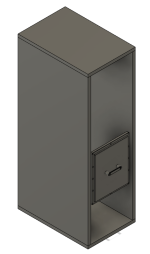
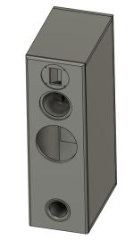
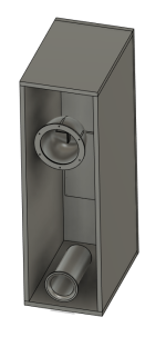
For all of those asking about the mid not being separate. Here are pics of the mid enclosure that will be 3d printed. This will isolate the two woofers from one another. I will have to play with the enclosure size to get it right but I see that mids do not require a very large enclosure space. Not sure I should just go with the size recommended by WinISD simluation for a flat response. That says 200 in cubed which seems very small to me
Attachments


That's more like it! Yes, mid will require small volume. Depends were you cross it. Better make it dagger like X in his builds. Just a suggestion.
If you can, wrap a layer (or two) of butyl rubber sound dampening material on the outside of the 3D printed enclosure. (The sticky sheets with aluminum backing common in automotive sound .) Otherwise the interior pressure of the woofer may bleed into the midrange.
A4e,
Can definitely do this. I have a bunch of that sound dampener stuff in my garage somewhere. I will be laser cutting a closed cell foam gasket to seal the mini enclosure to the back side of the baffle. I want no leaks.
Can definitely do this. I have a bunch of that sound dampener stuff in my garage somewhere. I will be laser cutting a closed cell foam gasket to seal the mini enclosure to the back side of the baffle. I want no leaks.
A4e means the whole surface area of the solid, I guess.
Some braces or honeycomb structure to prevent deformation ( worst case...)
Some braces or honeycomb structure to prevent deformation ( worst case...)
https://www.diyaudio.com/community/...-waw-ref-monitor.273524/page-206#post-7633567Adason,
What is "dagger like X"? I do not know this reference.
Yeah, 3d printing something is much easier than trying to do all of that
I can add some structural elements inside the enclosure bell to give it some rigidity as well as break up some of those high frequencies coming out of the back of the driver.
Might release it when I am done and then anyone can scale it up or down to whatever size they want for whatever driver they happen to need it for.
Just another suggestion...you might as well copy succesful designs. After all plagiarism is form of flattery. I would use two woofers. Many reasons...
I would not bother with separate 3d print, just make upper part for mid and tweeter separate with divider.
I would suggest bevelled top, as your huge study showed, that is best.
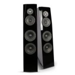
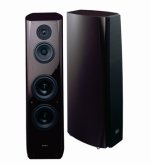
Here two examples of sleak well designed commercial 3way towers.
Good luck.
I would not bother with separate 3d print, just make upper part for mid and tweeter separate with divider.
I would suggest bevelled top, as your huge study showed, that is best.
Here two examples of sleak well designed commercial 3way towers.
Good luck.
Attachments
Last edited:
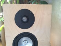
How close is too close for drivers? I know the closer they are together the better they will meld. These are pretty close though. For reference, this cabinet is 32" tall.
Yes. And your solution is fine ! That said, a vertical alignment instead would not change significantly the distances from axes to axes.
Here's my take on the subject :
The most important distance is Tweeter to Midrange, since it is the shortest wavelenght, so these two speakers have to be close as possible.
In theory ( Vance Dickason / Loudspeaker CookBook ), the distance between the center of two speakers should never exceed the wavelenght of the crossover transition frequency between these speakers :
FC = 1/2.(D/c)
D = c/2.FC
Where :
FC = Xover transition frequency (Hz)
D = distance between speakers centers (m)
c = sound celerity (circa 340m/s)
This condition is very difficult to meet between Tweeter and Midrange, so yes... The closest is the best by default ! For Woofer to Midrange, since the wavelength is larger, this condition is easier to satisfy.
For example :
TW to MR FC at 5000Hz ----> D = 340/(2.5000) = 0.034m = 34mm
Obviously, a distance of 34mm between MR and TW centers is nearly impossible to obtain. None of the pictured enclosures above meets this condition.
Even this another example below, despite its 200x200mm overall frontface dimensions, extra-compact tweeter (41x41mm) and 4" woofer-midrange, cannot follow :
MR to WF Fc at 400Hz ----> D = 340/(2.400) = 0.425m = 425mm
This shows no issue to respect this limit condition. On the first picture above, for the 3-Ways enclosure, D = 315mm, despite that the woofer is a 12" and the midrange is 8", for the considered FC at 400Hz.
T
Last edited:
I would have used 2 woofers........ but that would have increased the enclosure by double unless I went isobaric. Doubling the cabinet size was deemed unaccaptable to the wife.Just another suggestion...you might as well copy succesful designs. After all plagiarism is form of flattery. I would use two woofers. Many reasons...
I would not bother with separate 3d print, just make upper part for mid and tweeter separate with divider.
I would suggest bevelled top, as your huge study showed, that is best.
Here two examples of sleak well designed commercial 3way towers.
Good luck.
Iso is still on the table though. I tried some sims with isobaric and it wasn't as clean as a single woofer.
1) Isobaric: Until two months ago, the best speaker I had designed was isobaric so I'm not a hater. But they aren't very practical and are inefficient. If you need a much smaller cabinet, then they can make sense. In your case, you have a cabinet with one woofer that works fine but if you wanted to go two woofers the cab is too big. So a solution is to have a pair of isobaric woofers, i.e., 4 in each cab. I doubt the cost of 8 woofers vs 2 is worth it.
2) Center-to-center spacing (CtC): The conventional wisdom for a long time has been to have a CtC spacing less than 1 wavelength of the crossover frequency (I think I have seen 1/4 wavelength used too) and since that is usually not possible space as close as possible. More recently Kimmo (creator of VituixCAD) has shown that using a CtC of 1.0 to 1.4 x the wavelength provides a better vertical power response. Some people would actually build a prototype box with different spacing to get the best output. I think most of us build the actual cabinet and then live with any slight flaws. I usually have a pretty good idea of where I'm going to cross over, so I try to build with the CtC spacing of 1.2x that wavelength and live with whatever the final product comes out to be. (See THIS POST and also the post Hifijim links to)
2) Center-to-center spacing (CtC): The conventional wisdom for a long time has been to have a CtC spacing less than 1 wavelength of the crossover frequency (I think I have seen 1/4 wavelength used too) and since that is usually not possible space as close as possible. More recently Kimmo (creator of VituixCAD) has shown that using a CtC of 1.0 to 1.4 x the wavelength provides a better vertical power response. Some people would actually build a prototype box with different spacing to get the best output. I think most of us build the actual cabinet and then live with any slight flaws. I usually have a pretty good idea of where I'm going to cross over, so I try to build with the CtC spacing of 1.2x that wavelength and live with whatever the final product comes out to be. (See THIS POST and also the post Hifijim links to)
Super interesting. Ok, that all makes sense to me.
Thanks for clarifying that. It makes much more sense now.
As far as the woofers, yes, I determined it wasn't worth it to go double or iso. Maybe in a future build I will play around with that.
I have a design for the shop that uses an isobaric setup for a subwoofer. $180 worth of drivers and will hit super low. However, I have tons of space in my shop. Very little in my house.
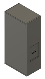
Alright, here is what I have. They are all aligned. Front facing port 3" diameter by 7.5 inch.
There is a removeable back panel. That is where the crossover will live. It seals flush from the inside so the pressure from the woofer will help seal it rather than try to push it out. I will have heat set inserts into that panel so I can use M4 bolts through the enclosure into that plate. The plate, port, handle, and mid woofer enclosure will all be 3d printed.
Anyone see any issues with this setup?
Attachments
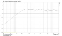
As to tweeter placement: a position in the middle of the baffle often ends up in some diffraction induced wiggles at higher frequencies in the on axis measurement. At 15 degrees off axis those mostly disappear. Putting the tweeter a tad to one side (like Heissmann showed) almost always leads to more straight on axis response, but the off axis response doesn't get necessarily better (some say worse).
I would avoid equidistances from center of the tweeter to sides and top of the baffle, unless using ribbons or planars that beam in the vertical plane. By carefully positioning the tweeter (for mids this is hardly necessary) you spread out the cancellations from virtual sources at the baffle edges. See attached baffle design and resulting response from 2,5k and up. Although edges are quite 'hard', on axis response is OK.
I would avoid equidistances from center of the tweeter to sides and top of the baffle, unless using ribbons or planars that beam in the vertical plane. By carefully positioning the tweeter (for mids this is hardly necessary) you spread out the cancellations from virtual sources at the baffle edges. See attached baffle design and resulting response from 2,5k and up. Although edges are quite 'hard', on axis response is OK.
Attachments
- Home
- Loudspeakers
- Multi-Way
- How close can I put drivers in an enclosure?