That means you would need to probe each stage with an oscilloscope or signal tracer to find out which part of the circuit is causing the problem.
That's exactly what I want to do, but I don't know how. I'm looking for either an explanation, or a guide, or something.
Man, I just looked on Ebay for signal tracers, and they want an arm and a leg for most of them...
Here's a link to the manual and schematic for the ARC SP-10, for whatever good it'll do ya... It's a complex SOB.
https://audioresearch.com/wp-content/uploads/2021/08/SP10_Manual_Schem.pdf
https://audioresearch.com/wp-content/uploads/2021/08/SP10_Manual_Schem.pdf
Yeah, it is. I picked an expensive, complicated amp to learn on.
With any kind of tracing, where do I connect the ground lead? I have a guitar amp, and an oscilloscope that I can use to trace.
With any kind of tracing, where do I connect the ground lead? I have a guitar amp, and an oscilloscope that I can use to trace.

I assume that the SP10 has a decent isolation transformer to power it, rather than a "sudden death" chassis (according to the manual, it does have a proper power transformer, so you have some isolation). You probably want to get a 100X probe to do your poking around - you can find them relatively cheap on E-pray. Clip your ground to the B+ common, set your scope for AC coupled, and start at 100V/div and work your way down, probing each successive stage from input to output. Which input setting is the noisy one, pray tell?
Thanks @rayma , @wrenchone.
It's the phono input, especially the right channel. The 1k resistors seem to be the most "lively" when I spray them.
Why do you suggest a 100x probe? 10x would bring the 300v B+ down to just 30v. Or are you thinking of shorts?
It's the phono input, especially the right channel. The 1k resistors seem to be the most "lively" when I spray them.
Why do you suggest a 100x probe? 10x would bring the 300v B+ down to just 30v. Or are you thinking of shorts?
Let me see if I get this, somebody who couldn’t fix your problem told you you have a bad resistor, but they couldn’t find it or fix it.
I would first resolder all of the connections on the PCB. A bad solder joint is the most likely cause of noise.
The image you posted shows some not so good soldering.
Unplug the power cord first. With a warm temperature controlled iron you just remelt the joints at the same time as adding a very tiny bit of new solder. Preferably 63/37 tin/lead solder.
That should take only a few minutes. If that doesn’t get it, the next try is to swap tubes between channels. If not possible then identical tubes between gain stages.
Last edited:
No, not even close.Let me see if I get this, somebody who couldn’t fix your problem told you you have a bad resistor, but they couldn’t find it or fix it
I’ve already tried swapping the tubes, the noise doesn’t follow the tube
I’ll try re-soldering, good idea. What’s the purpose of the tiny amount of new solder? Does it make a better “alloy” with the old solder?
Then why do you think the problem is a resistor?
Adding a bit of solder reduces the chances of a cold solder joint.
Adding a bit of solder reduces the chances of a cold solder joint.
Based on the type of noise/distortion/etc, and the fact that swapping tubes didn’t help. Replacing resistors that reacted to the freeze spray was successful on another similar amplifier of similar age.
I never thought of reflowing the solder joints… replacing a resistor would have the same effect. Maybe the new parts didn’t even effect the outcome!
I never thought of reflowing the solder joints… replacing a resistor would have the same effect. Maybe the new parts didn’t even effect the outcome!
As far as the attached image can be trusted, I second what simon7000 wrote....
The image you posted shows some not so good soldering.
...
Attachments
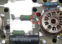
Oooh, thank you for identifying that! Now I have a better idea what to look for. Tomorrow I'll go resolder everything and see if it makes a difference. Would be lovely not to have to change any parts.
You can "test" individual components with freeze spray, it is just a bit more time consuming then spraying the whole board. I have done that before to find smd capacitors that are "microphonic". Put the long tube in the head of the can freeze spray. Now hold the can with the tube sloping 45° (or so) down and push very gently on the button so it doesn't spray but dribbles. Do this a bit until you have a droplet of the fluid at the end of the tube. Now just touch the component you want to test with that droplet.I’ve been using freeze spray to identify resistors that are cold sensitive, but I’d like to be able to test individual components.
Broken or sensitive component with react to the sudden cooling. And because of using just a droplet you know which component it is you touched.
- Home
- Design & Build
- Construction Tips
- How can I test for a noisy resistor in-circuit?