Could you suggest another tube .. remember the other triode is running at only 1ma at a plate voltage of 144V
scratch that, I see you did...
It is probably best not to push this triode too hard as it looks like a unity gain buffer before the tonestack...
here is a flowchart
DO you think changeing the 56K resistor to an R + variable R would provide another control over the distortion...
Obviously for guitar a nice variety of distortion is appreciated... but I will listen to your words and make sure to keep the amp in safe operating area.. This baby wil do lots of metal duty... and will sit just before a Big Muff Pi derivative to bring the distortion into the 21st century as well as adding sustain.
scratch that, I see you did...
It is probably best not to push this triode too hard as it looks like a unity gain buffer before the tonestack...
here is a flowchart
An externally hosted image should be here but it was not working when we last tested it.
DO you think changeing the 56K resistor to an R + variable R would provide another control over the distortion...
Obviously for guitar a nice variety of distortion is appreciated... but I will listen to your words and make sure to keep the amp in safe operating area.. This baby wil do lots of metal duty... and will sit just before a Big Muff Pi derivative to bring the distortion into the 21st century as well as adding sustain.
Disclaimer: I don't have any experience in instrument amps. For hifi use, I'd tend toward an ECC88 or ECC81 for normal requirements. 2.6mA is not unreasonable there.
I'd be inclined to control distortion elsewhere, probably in a voltage amp stage. But if an experienced IA designer recommends otherwise, listen to him, not me.
I'd be inclined to control distortion elsewhere, probably in a voltage amp stage. But if an experienced IA designer recommends otherwise, listen to him, not me.
Hi SY obviously, hifi is not what we are aiming at here and I guess some of the old "effects"we love come form just such unoptimised designs, this one is from a commercial, well loved product of the 70s, vut ca also be adjsuted to get close to the Ibanez tubscreamer sound... also reminicent of old Marshall amps.
Now if I could figure out all the switches in the schematic I would build a Mesa Boogie Dual Rectifier...
PS I have some ECC88 and E188cc
PS I just looked at at datasheet that quotes 1.2mA plate current?
Now if I could figure out all the switches in the schematic I would build a Mesa Boogie Dual Rectifier...
PS I have some ECC88 and E188cc
PS I just looked at at datasheet that quotes 1.2mA plate current?
Good morning Nordic,
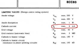
the ECC 83 can handle up to 8mA. 🙂
http://frank.pocnet.net/index.html
 It makes me sad, some people don't tell
you the truth here in this forum.🙁
Keep your eyes open! 😉
Kind regards,
Darius
the ECC 83 can handle up to 8mA. 🙂
http://frank.pocnet.net/index.html
It makes me sad, some people don't tell you the truth here in this forum.🙁
Keep your eyes open! 😉
Kind regards,
Darius
Attachments
Many thanks for the kind replies....
I have spent some time reading up a bit again, looking at similar scehematics showing other details etc...
It is clear the setup is for very couloured sound and on high level settings should cause quite a bit of compression and assymetric clipping - GOOD...
Am I right that makeing the 56k on the last cathode switchable with higher impendances, that I would add another range of "effects" or diffirent "sounding" settings... or at least bring on clipping at various levels ...
I am aiming for organic transition between slightly and very distorted on peak signals.... by simply playing harder... (would love to have some output valve clipping but that is out of the budget for now...)
The goal, a heavy metal box of horrors....
Now, I need some help on the existing schematic (laid out to make more sense as haveing a switchable dirty and clean channel).
I am not realy sure if I got the pins correct on the tonestack pots... I connected pin 1 and 3 in the way that seemed logic... even played with duncan's tonestack jobby...but could not figure out the order of those 2 pins on the sides of those pots...
Also if powering the fillaments in parallel... which (should any) of the heater filaments be connected to ground....? would it be ok to make a split supply of 3.x V just useing 2 caps and 2 resistors to form a relative floating ground and connect that to star ground....?
I managed to get my questions answered to some extent on the interwebs...
But I have some new ones
As the cathode in the last triode is at over 144V, does the heater voltage need to be lifted?
If so.. how does this interact with the other half of the tube where the cathode is pretty close to ground...?
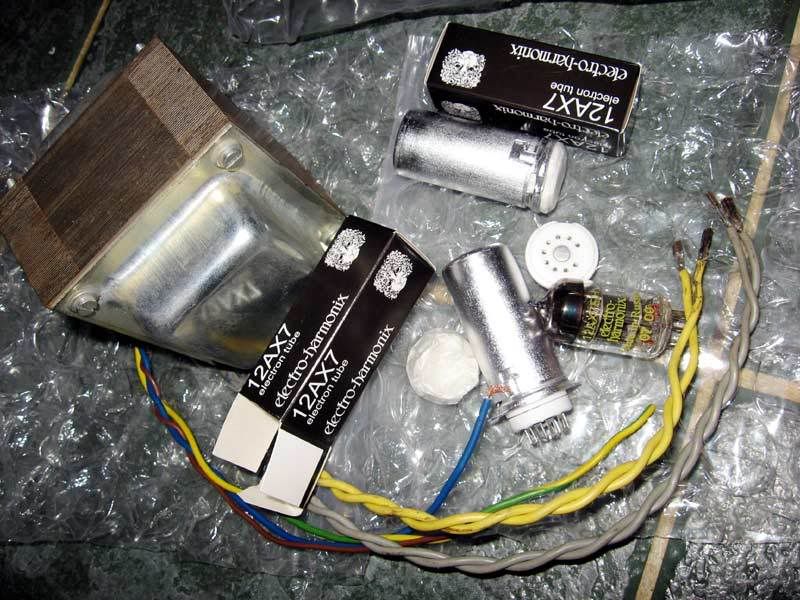
Here is a photo... my tubes and transformer (made by Peter Sourris) arrived this morning..
output 200V 100VA, and 12V @ 2A
But I have some new ones
As the cathode in the last triode is at over 144V, does the heater voltage need to be lifted?
If so.. how does this interact with the other half of the tube where the cathode is pretty close to ground...?
Here is a photo... my tubes and transformer (made by Peter Sourris) arrived this morning..
output 200V 100VA, and 12V @ 2A
- Status
- Not open for further replies.
- Home
- Amplifiers
- Tubes / Valves
- How can I calculate voltage over cathode resistor?