I've had some problems supplying my voltage regulator with rectified DC power. My rectifier designs always seem to arc over and short out.
My transformer is a Hammond 712, 293 VA 850 CT and 345 mA.
My diodes are DIODE FRED 1.2KV 8A TO220AC
and the capacitor is a Solen Film 51uF 1500Vdc PESG-CAN Series
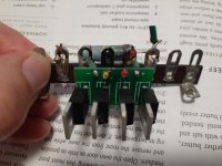
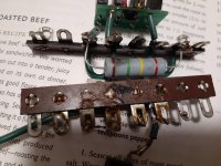
At first I'd tried a point to point design but after the first flame out I went with a PCB that I got from parts connexion for the next four attempts.
Here are a couple of photographs of the latest flame out from today, as well as my first attempt (the point to point.) Today the electricity went across the PCB, usually my problem is the electricity arcing across the terminal lug strip. This is the fifth time now so I think I need to try something different.
I have trouble understanding why the electrons would travel across the plastic or press-board rather than through the wire. I would have thought there would be much less resistance in the metal.
Any suggestions or criticisms would be welcome.
Thanks,
Glenn
My transformer is a Hammond 712, 293 VA 850 CT and 345 mA.
My diodes are DIODE FRED 1.2KV 8A TO220AC
and the capacitor is a Solen Film 51uF 1500Vdc PESG-CAN Series
At first I'd tried a point to point design but after the first flame out I went with a PCB that I got from parts connexion for the next four attempts.
Here are a couple of photographs of the latest flame out from today, as well as my first attempt (the point to point.) Today the electricity went across the PCB, usually my problem is the electricity arcing across the terminal lug strip. This is the fifth time now so I think I need to try something different.
I have trouble understanding why the electrons would travel across the plastic or press-board rather than through the wire. I would have thought there would be much less resistance in the metal.
Any suggestions or criticisms would be welcome.
Thanks,
Glenn
Attachments

I see your diodes are TO220 case styles...no heatsinks? did you derate them?
I'd up the ratings, beyond your 1.2KV you have...I would abandon this sliver of a PC board & go with a full-on point to point arrangement.
Heat is always an Achillies heel.
------------------------------------------------------------------------Rick.......
I'd up the ratings, beyond your 1.2KV you have...I would abandon this sliver of a PC board & go with a full-on point to point arrangement.
Heat is always an Achillies heel.
------------------------------------------------------------------------Rick.......
....850 CT .... 1.2KV...
In the FWB, the peak is 2.8 times the V(rms). You need 2.4KV parts. (I think.)
Even if I am wrong, you are within 1% of diode rating, and you know that 850 will vary.
850 volts AC is 1.414 x 850 or 1202 volts peak. That assumes your line voltage actually matches the transformer primary voltage. Then there is the issue of voltage spikes caused by motors etc stopping or starting.
Of course in a bridge you have two diodes effectively in series and the AC voltage peak to peak would be 2404 volts.
Nice to see the diodes meet their ratings quite accurately!
Of course in a bridge you have two diodes effectively in series and the AC voltage peak to peak would be 2404 volts.
Nice to see the diodes meet their ratings quite accurately!
850 V~ is 1202 V peak. Transformer output tends to be a good bit higher when not loaded, and you may be looking at 1.5 kV peak then. (I'm not even talking about transients coming in from the mains. You better use a mains filter.) That's high voltage and not to be taken lightly.
You should probably look into clearance and creepage requirements some more. Here are some pages a quick search turned up:
PCB Trace Spacing Calculation for Voltage Levels
Clearance and Creepage Rules for PCB Assembly
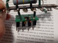
It looks like creepage distance between the AC input terminals on the rectifier board may not be adequate. You may be able to salvage this one by cutting a notch into it right there.
You should probably look into clearance and creepage requirements some more. Here are some pages a quick search turned up:
PCB Trace Spacing Calculation for Voltage Levels
Clearance and Creepage Rules for PCB Assembly
It looks like creepage distance between the AC input terminals on the rectifier board may not be adequate. You may be able to salvage this one by cutting a notch into it right there.
I didn't think I needed a heat sink. But that seems like I good idea. I'm not sure what you mean by derate. If it means to calculate whether or not I needed a heat sink, that's not something I know how to do. But putting on a little thermal paste and a heat sink, just to be on the safe side, is something I know how to do.
I thought a PCB board would be better than point to point, but you guys are right when you point out how crowded the PCB board is. At 425-0-425 I thought 1.2 kV would be ok but I'm new to this and I'm willing to learn...thanks. I'll see about getting diodes with a higher rating.
I thought a PCB board would be better than point to point, but you guys are right when you point out how crowded the PCB board is. At 425-0-425 I thought 1.2 kV would be ok but I'm new to this and I'm willing to learn...thanks. I'll see about getting diodes with a higher rating.
Ok, I've read all the posts now and I'm definitely going to get diodes with a higher rating.
Thanks for helping and teaching me a thing or two about diodes.
Thanks for helping and teaching me a thing or two about diodes.
Given the arcing is across the AC input pads, and as sgrossklass indicates, the creepage spacing on your pcb appears to be the smallest distance at that location. Another option than cutting a notch is to trim the two pads back as much as practical to increase the creepage. After soldering, ensure no solder encroaches on that creepage/clearance region, and clean the area with IPA, and avoid dust getting in there.
You may also need to do that for the AC to DC terminals creepage distances as well on that pcb.
Did you make the pcb yourself?
You may want to elaborate on what diodes you are going to change to, as the current rating may not be a concern at all.
You may also need to do that for the AC to DC terminals creepage distances as well on that pcb.
Did you make the pcb yourself?
You may want to elaborate on what diodes you are going to change to, as the current rating may not be a concern at all.
Last edited:
Your diodes also need to take - rectified voltage so they can have double rectified voltage across them.
I suspect they are burning out because the yare grossly under rated for the job.
I suspect they are burning out because the yare grossly under rated for the job.
I bought the PCB from parts connexion.
Discrete Bridge Rectifier PCB - TYPE 2 (TO-220 Radial Style)
I think I'll be doing the next one as a point to point.
Here's the diodes I'm looking at now.
Blocked
DIODE AVALANCH 2.4KV 350MA SOD57
This looks like it will work.
Discrete Bridge Rectifier PCB - TYPE 2 (TO-220 Radial Style)
I think I'll be doing the next one as a point to point.
Here's the diodes I'm looking at now.
Blocked
DIODE AVALANCH 2.4KV 350MA SOD57
This looks like it will work.
Two diodes in series will also work here. In series the voltages add up, so you’d be at 2.4Kv. That can jump a good distance! Make sure traces are at least 4mm apart and use a heat sink for each diode that are separate and not close to each other. You are literally playing with fire here!
I suggest that is not a good replacement diode choice due to the reverse recovery time, and possibly the current rating. You may be far better off with 2 x UF4007 in series for each bridge 'diode'. But you haven't identified your load requirement, which is required to clarify what diode current rating is reasonable.
The OP has not clarified if any diode has failed, and as I interpret it, has only confirmed that there was arcing across the pcb in the region between the AC terminals.
Diodes may have degraded and that may not have been measurable by the OP.
If diode(s) had failed then at that would either cause higher ripple, or at worst some level of short-circuit across the transformer secondary.
PS. Does the OP realise that he may be accidentally applying a bridge rectifier to his transformer to generate a single DC output, rather what looks like the intent was to make a full-wave rectifier using the 450-0-450 secondary, or to make a full-bridge but withe CT connected to a split capacitor filter output ? Perhaps best to provide a schematic of what has been made.
Trobbins you've gone above and beyond my understanding.
Let me provide you some more information. The load is a neurochrome 21ST CENTURY MAIDA REGULATOR (I think that's what you were asking me). It is a voltage regulator that I am using to power a tubelab Simple single ended amplifier (SSE.) My goal is to have a B+ of 450V on my amp.
Are you asking me to draw a schematic of the rectifier I was using to provide DC power to the voltage rectifier?
I'd made a full wave bridge capacitor input load rectifier. Would a full wave capacitor input load rectifier have been a better choice?
I'll draw the schematic tomorrow, I'm trying to figure out some homework for my son right now (somehow I had this feeling that once I had graduated high school I would never have high school homework again....boy was I wrong!!!)
Attachments
It is ambiguous as to whether you wired your 425-0-425V transformer (which you also refer to as 850 CT) as per the Hammond Guide for Full Wave Capacitor Input Load (where Vdc av is about 0.45 x 2 x 425 = 380V), or with Full Wave Bridge Capacitor Input Load (where Vdc av is about 0.9 x 850 = 770V).
Or as per dual full-wave that initially looks like a bridge with CT.
https://sound-au.com/psu-f6.gif
Or as per dual full-wave that initially looks like a bridge with CT.
https://sound-au.com/psu-f6.gif
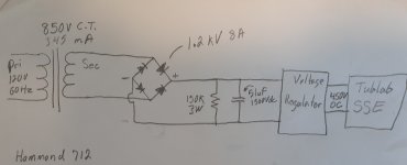
Here's a schematic of what I did.
The transformer is listed as 850V 345 mA. Because it has 2 wires that connect to the primary and 3 that come out of the secondary I'd thought that was 425-0-425. I even thought it was in the specs. It is not. Lesson learned!
Yes, there was arcing across the pcb in the region between the AC terminals. And you're right I'm not able to measure if there's damage to the diodes. I'll just play it safe and buy some new ones.
It's alarming to hear I might have damaged the transformer. The ends of the wire coming from the secondary of the transformer were blackened. Is there any way to check for damage. A visual inspection only turns up the previously mentioned blackened ends.
I don't really understand the PS part. But I can tell you that there are 3 wires that come out of the secondary. 2 red and 1 yellow. I had connected 1 red and the yellow to the bridge rectifier. Could this be what you're referring to when you say " or to make a full-bridge but withe CT connected to a split capacitor filter output ?" I had initially used both red wires but had been advised to try one red and one yellow. It seemed to work for a while but it flamed out and arced over as I was trying different things to solve a grounding issue I was having.
The transformer is listed as 850V 345 mA. Because it has 2 wires that connect to the primary and 3 that come out of the secondary I'd thought that was 425-0-425. I even thought it was in the specs. It is not. Lesson learned!
Yes, there was arcing across the pcb in the region between the AC terminals. And you're right I'm not able to measure if there's damage to the diodes. I'll just play it safe and buy some new ones.
If diode(s) had failed then at that would either cause higher ripple, or at worst some level of short-circuit across the transformer secondary.
PS. Does the OP realise that he may be accidentally applying a bridge rectifier to his transformer to generate a single DC output, rather what looks like the intent was to make a full-wave rectifier using the 450-0-450 secondary, or to make a full-bridge but withe CT connected to a split capacitor filter output ? Perhaps best to provide a schematic of what has been made.
It's alarming to hear I might have damaged the transformer. The ends of the wire coming from the secondary of the transformer were blackened. Is there any way to check for damage. A visual inspection only turns up the previously mentioned blackened ends.
I don't really understand the PS part. But I can tell you that there are 3 wires that come out of the secondary. 2 red and 1 yellow. I had connected 1 red and the yellow to the bridge rectifier. Could this be what you're referring to when you say " or to make a full-bridge but withe CT connected to a split capacitor filter output ?" I had initially used both red wires but had been advised to try one red and one yellow. It seemed to work for a while but it flamed out and arced over as I was trying different things to solve a grounding issue I was having.
Attachments
It is a voltage regulator that I am using to power a tubelab Simple single ended amplifier (SSE.) My goal is to have a B+ of 450V on my amp.
I don't understand why the center tap isn't used on this transformer with a 2-diode rectifier.
You'd get the required voltage, and then some.
Simple.
It's the way it was always done.
- Home
- Amplifiers
- Power Supplies
- How can I build a bridge rectifier that will last?