You could do 1.7 (red) x4 and a single green (2.0). Or just get something close and not worry about it- it's a low mu tube so the operating point won't be terribly disturbed by half a volt either way.
LED's caused bad hum
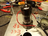
I tried a couple of Red LED's on an amp I have on the board (5Y3, 6SN7, 6BQ5, SE, Pentode Mode).
Using the traditional RC the amp is dead quiet. When I switched to LED's I picked up a hum.
I have no idea what the LED's are. I have had them laying around for years.
I tried a couple of Red LED's on an amp I have on the board (5Y3, 6SN7, 6BQ5, SE, Pentode Mode).
Using the traditional RC the amp is dead quiet. When I switched to LED's I picked up a hum.
I have no idea what the LED's are. I have had them laying around for years.
Hum went away.
When I connect them the second time it hummed for 1/2 second and stopped. Now It works fine.
Strange! Self correcting amp?
When I connect them the second time it hummed for 1/2 second and stopped. Now It works fine.
Strange! Self correcting amp?
Hum went away.
When I connect them the second time it hummed for 1/2 second and stopped. Now It works fine.
Strange! Self correcting amp?
What do you prefer subjectively speaking: LEDs or RC?
Strange! Self correcting amp?
Or soldering. Or accidental short to something else.
FWIW, I have LEDs in the first stage of my phono preamp and it's a pretty darn quiet unit.
Sounds like an AM modulator.....in the creationUsing the traditional RC the amp is dead quiet. When I switched to LED's I picked up a hum.
One runs the risk of oscillation using high gm tubes or lanky wiring; the tube using an LED in the CCS sees a fantastically high AC impedance compared to the resistive damper, this aggravates the AC parasitics around the tube into oscillation.
For example; Experiments using a 12BY7 a flightly high gm video pentode quoted with a moderate plate resistance was found stable with a particular circuit (CCS in cathode); replacing with a tube with a higher plate resistance i.e a 6CL6, oscillation immediately broke out but the LF signal still passed.
Tempting advantages of using LED in the CCS circuit, check with a scope that oscillation isn't breaking out on large AC voltage signal excursions approaching cutoff and that the scope probe capacitance isn't swamping the oscillations out.
Ye higher the ft, more hidden problems appear. A favourite self oscillation frequency of many B9A type tube circuits seems to be around 4-7MHz
(ECC88 around 400MHz) and all scopes using the RF "sniffler" loop of wire direct into coax to scope input will pick the lower frequencies up..without touching the high impedance circuit.
....RF love it....but without experience can be nasty.
Be safe, use CCS with lower gm pentodes or even safer, triodes.
richy
Attachments
If you mean "resistor bypassed with big electrolytic," then better overload recovery, lower cost, flatter gain/phase at low frequencies, potentially lower distortion (if one believes that capacitors impart certain sonic characteristics). And of course, a visual indication that a stage is operating. If you mean "just resistor," add lower source impedance, higher gain, lower order distortion spectrum.
SY, could you quickly explain overload recovery to me please? From reading off your website and on this forum I understand a little....
... but I don't quite understand what it needs to recover from.
When a signal clips does it push the stage into an unstable state of some kind, and the LED brings this back to normal quicker than a bypassed resistor? That's pretty much all ive got mate.... is that nearly right?
Cheers
Close. When a tube clips, it draws grid current. This causes an overbias condition- then, when the input signal drops below the clipping level, the cap at the cathode is still charged at the overbias voltage. It discharges via the parallel combination of the cathode resistor and the cathode impedance. That time constant is likely to be on the order of a large fraction of a second so that the clipping "event" is extended from a few milliseconds to several hundred milliseconds or more.
With a LED, that cathode voltage never significantly rises in the first place- think of it as being equivalent to a battery there.
With a LED, that cathode voltage never significantly rises in the first place- think of it as being equivalent to a battery there.
That's really interesting. Several hundred milliseconds seems like a long time in audio. So in a bypassed resistor stage, when the valve clips it takes time (several hundred milliseconds) before it will operate as it's meant to?
And do you notice a difference sonically in this overload recovery? Can you tell when an amp isn't recovering from overload fast enough, or is it more a subjective or a performance thing...?
Cheers
And do you notice a difference sonically in this overload recovery? Can you tell when an amp isn't recovering from overload fast enough, or is it more a subjective or a performance thing...?
Cheers
Yes, it's very clearly audible; the amp sounds like it's choking. Get rid of the problem and the clipping becomes a much more subtle effect. There's a Norman Crowhurst paper floating around (it was originally published in Audio in 1959) about this very issue, so-called "blocking," complete with detailed analysis and illustrations. Reprinted in Audio Amateur back in the '80s, might be in Audio Anthology. If I can dig up a copy, I'll either post it here or as a link on my website. Title was something like "Amplifier Characteristics Not Covered by Normal Specifications."
This is also discussed at length in Morgan Jones's book.
edit: I misremembered the title- that was yet another excellent paper by Crowhurst. The one which covered blocking was "Puzzled About Amplifiers?" It was reprinted in Audio Anthology 5.
This is also discussed at length in Morgan Jones's book.
edit: I misremembered the title- that was yet another excellent paper by Crowhurst. The one which covered blocking was "Puzzled About Amplifiers?" It was reprinted in Audio Anthology 5.
This is also discussed at length in Morgan Jones's book.
I'll keep reading...
Thank you
- Status
- Not open for further replies.
- Home
- Amplifiers
- Tubes / Valves
- How calculate cathode LEDs biased