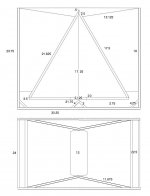
I got this La Scala look alike. It uses a 12" driver and the throat is 260x200 mm otherwise very similar to the bass section of the LaScala.

The horn, some drivers, 70x70 triangular wood cut to lenght and XTZ Room Analyzer II. Install various combinations of drivers and reflectors.What could go wrong🙄
First out of the gate is the Beyma G320 made for midbass horns.

Adding the bisecting reflector in front of the driver does not frequency response at all below 1 kHz. (Green is with no reflectors)
Removing the reflector and adding reflectors on the second bend. Then I gor a minor boost at 1 kHz and an enourmous boost 1.5 to 2 kHz

Adding all reflecors should add some more..

Surprise, back to square one more or less.

The Fr and Q are system not driver really
In with a Fane Crescendo 80W driver, and there I get a boost from adding the bisecting reflector.

Adding the corner reflectors gets the response allmost back to square one apart from a couple of dB between 250-700 Hz.

I expected adding more reflectors would add more high frequency response and even it out as well in a simple additative fashion.
Instead I get all kind of complex interaction between drivers and the reflectors.
Are there any rules to this game? If not I have to build all horns that is not a proven combination of driver and horn, with no reflectors and then fiddle around with different combinations until I find the one that sounds best😱
The horn, some drivers, 70x70 triangular wood cut to lenght and XTZ Room Analyzer II. Install various combinations of drivers and reflectors.What could go wrong🙄
First out of the gate is the Beyma G320 made for midbass horns.
Adding the bisecting reflector in front of the driver does not frequency response at all below 1 kHz. (Green is with no reflectors)
Removing the reflector and adding reflectors on the second bend. Then I gor a minor boost at 1 kHz and an enourmous boost 1.5 to 2 kHz
Adding all reflecors should add some more..
Surprise, back to square one more or less.
The Fr and Q are system not driver really
In with a Fane Crescendo 80W driver, and there I get a boost from adding the bisecting reflector.
Adding the corner reflectors gets the response allmost back to square one apart from a couple of dB between 250-700 Hz.
I expected adding more reflectors would add more high frequency response and even it out as well in a simple additative fashion.
Instead I get all kind of complex interaction between drivers and the reflectors.
Are there any rules to this game? If not I have to build all horns that is not a proven combination of driver and horn, with no reflectors and then fiddle around with different combinations until I find the one that sounds best😱
There is more than one about reflectors. Bruce Edgar discuss this in several of his publications. Then there is Bill Fitzmaurice advocating smooth curvy bends. Mine is close to the diagonal reflectors, as this was cheap and ready at the lumber yard.
At 1kHz a quarter wavelengh is less than 10 cm so break up pattern of the cone and such things will affect what is sent down the throat and in what phase shift. I am sure that there is a lot to be done in different throat geometries for the output in the 500-1000 Hz region. I might get into that but my prime objective was to play around with the horn and then deflectors came up.
I added some crude braces inspired by Klipsch La Scala Upgrades - Restoration. My braces does not extend all the way to the front so there remain quite a lot of vibration in the front "side lips" in front of the braces.
Looks like a Peavey FH-1 try an Altec 515. This is going to be good to about 450 500 Hz why would you want to run it higher than that when you can switch to a straight horn? the matching CH-1 horn will run from 350 Hz up in a home set up with a Peavey 22A one inch exit (2 inch diaphragm) driver. the woofer will be so;id down to 80 Hz with output to 45 but much rolled off. This is very much the same as a Klipsch Belle with being truncated. Nice horn. Best regards Moray James.
Horn Passage Folding & Bifurcation
The issue with these has to do with maintaining the horn’s pass-band.
The high frequency limit is determined by bend width [Wb].
At the lower bound, efficiency robbing air turbulence is addressed by passage smoothness.
Note that for smooth bends, where wavelength [Lw] > 2*[Wb], wave fronts will travel around them essentially undisturbed.
Of course, other response ripple issues determined by horn length and mouth perimeter remain.
Also see my post:
http://www.diyaudio.com/forums/pa-systems/173677-dual-18-pa-subs-live-sound-club-3.html#post2310734
Looks like a Peavey FH-1 try an Altec 515. This is going to be good to about 450 500 Hz why would you want to run it higher than that when you can switch to a straight horn? the matching CH-1 horn will run from 350 Hz up in a home set up with a Peavey 22A one inch exit (2 inch diaphragm) driver. the woofer will be so;id down to 80 Hz with output to 45 but much rolled off. This is very much the same as a Klipsch Belle with being truncated. Nice horn. Best regards Moray James.
Claude over at the Klipsch forum is using Electrovoice EVM 15L says the bottom end is a tad less but overall detail is very much improved he is quite thrilled with them. Claude has a K402 on top by the way, nice rig. Best regards Moray James.
<meta name="description" content="Klipsch audio systems provide the true audio/video lover a wide variety of high performance loudspeakers and loudspeaker systems for music and home theater entertainment centers, including iPod speakers, multimedia s
The accoustic lenght in bends is shorter than the geometric midline. This suggest that the bulk of the soundwave propagates in the inside half of the curve. Then the main smoothing of the curve should be on the inside of the bend.
I think that we as very visually oriented animals think in optical terms with regard to reflections. And for light to get around a 90 degree bend a 45 degree flat reflector is the right implement. But sound waves are not rays of light, so the analogy might not enlight us😀
I think that we as very visually oriented animals think in optical terms with regard to reflections. And for light to get around a 90 degree bend a 45 degree flat reflector is the right implement. But sound waves are not rays of light, so the analogy might not enlight us😀
Variable
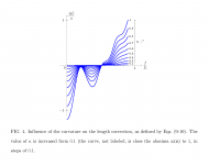
For a given cross-section, the acoustical length of a bent horn passage is a function of frequency and bend severity. As shown in the attached figure 4, it may be more, less or equal to that of an equivalent straight segment.
Regards,
WHG
Note:
Bend Curvature [K] = [a]/[R0]
where:
[a] - Tube Inside Radius
[R0] - Bend Axis Radius of Curvature
The accoustic lenght in bends is shorter than the geometric midline. This suggest that the bulk of the soundwave propagates in the inside half of the curve. Then the main smoothing of the curve should be on the inside of the bend.
For a given cross-section, the acoustical length of a bent horn passage is a function of frequency and bend severity. As shown in the attached figure 4, it may be more, less or equal to that of an equivalent straight segment.
Regards,
WHG
Note:
Bend Curvature [K] = [a]/[R0]
where:
[a] - Tube Inside Radius
[R0] - Bend Axis Radius of Curvature
Attachments
Last edited:
Attachments
Last edited:
whgeiger thanks for the info.
I am not sure that I understand the graph
Kappa, the more curvature the more influence of the bend (sounds resonable)
Delta L increase with increasing f/fc ratios but it is not asymptotic but has a null both at 0.25 and 0.5 ratios.
What is f and fc?
I am not sure that I understand the graph
Kappa, the more curvature the more influence of the bend (sounds resonable)
Delta L increase with increasing f/fc ratios but it is not asymptotic but has a null both at 0.25 and 0.5 ratios.
What is f and fc?
Addendum
Hi DB,
The information provided earlier comes from a recent and comprehensive work [1] on the subject.
Of note, is the accuracy between predicted vs. measured outcomes. To apply this regimen to folded loudspeaker horn design, will require study of the references given in the paper as well others.
Fig. 4 was extracted from the ASA paper [1]
[fc] = [j’11]*[c0]/(2*[pi]*[a]) Cutoff frequency of first superior (transverse) mode in the tube.
where
[c0] – sound velocity
[j’nk] = [j’11]=1.8412 – Root of a Bessel Function Derivative [2]
[a] – tube radius
Regards,
WHG
References:
[1] Effects of Bending Portions of the Air Column on the Acoustical Resonances of a Wind Instrument
Effects of bending portions of the air column on the acoustical resonances of a wind instrument | Browse - Journal of the Acoustical Society of America
http://hal.archives-ouvertes.fr/doc...rveen_Dalmont_2011_JAcoustSocAm_submitted.pdf
[2] Bessel Function Zeros
Bessel Function Zeros -- from Wolfram MathWorld
whgeiger thanks for the info.
I am not sure that I understand the graph
Kappa, the more curvature the more influence of the bend (sounds resonable)
Delta L increase with increasing f/fc ratios but it is not asymptotic but has a null both at 0.25 and 0.5 ratios.
What is f and fc?
Hi DB,
The information provided earlier comes from a recent and comprehensive work [1] on the subject.
Of note, is the accuracy between predicted vs. measured outcomes. To apply this regimen to folded loudspeaker horn design, will require study of the references given in the paper as well others.
Fig. 4 was extracted from the ASA paper [1]
[fc] = [j’11]*[c0]/(2*[pi]*[a]) Cutoff frequency of first superior (transverse) mode in the tube.
where
[c0] – sound velocity
[j’nk] = [j’11]=1.8412 – Root of a Bessel Function Derivative [2]
[a] – tube radius
Regards,
WHG
References:
[1] Effects of Bending Portions of the Air Column on the Acoustical Resonances of a Wind Instrument
Effects of bending portions of the air column on the acoustical resonances of a wind instrument | Browse - Journal of the Acoustical Society of America
http://hal.archives-ouvertes.fr/doc...rveen_Dalmont_2011_JAcoustSocAm_submitted.pdf
[2] Bessel Function Zeros
Bessel Function Zeros -- from Wolfram MathWorld
- Status
- Not open for further replies.
- Home
- Loudspeakers
- Multi-Way
- Horns and bend reflectors