I am trying to design a horn for a Fostex FE108EZ with hornresp but I am unsure what the sensitivity target should be.
The speakers sensitivity is 90 dB, so should the hornresp horn sensitivity be around that same level 2pi?
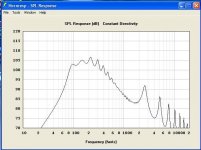
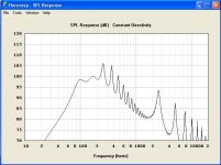
I have one designed that looks pretty flat and would work size wise but the simulated sensitivity between 80 and 300 hz is around 102dB. Would this mean that the midbass would be massively louder than the rest of the frequency range, or would adding stuffing etc tame it down a bit?
Thanks!
The speakers sensitivity is 90 dB, so should the hornresp horn sensitivity be around that same level 2pi?
I have one designed that looks pretty flat and would work size wise but the simulated sensitivity between 80 and 300 hz is around 102dB. Would this mean that the midbass would be massively louder than the rest of the frequency range, or would adding stuffing etc tame it down a bit?
Thanks!
That's good if the horn bass output is high in the design. It will tend to be lower once in practice and you can always add stuffing to balance. Much better to have too much to start rather than not enough. Post the HR output and plan if you want feedback on the design.
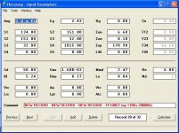
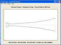
Alright there they are. Which do you think would be easier to tune with some stuffing for a flat response?
I just need to get to 80 Hz so the sub section can take over
I just need to get to 80 Hz so the sub section can take over
They are not. The results I was getting were pretty unbelievable so I didn't think they were relevant for this kind of design. I'll post them in a second

The first one is better, however much of the sharp peaks will be damped out if you add corners and sharp bends in folding the horn, or use stuffing. Varying the ratio of the driver chamber volume vs the throat area will change the higher frequency peaks.
Will the stuffing attenuate it 12 db? That just seems like a big difference between the majority of the range and the mid bass. If I could make the second one work and smooth out those peaks it would be ideal, it is much smaller.
I was planning on having at least 1 sharp fold (180 degrees), and heavily stuffing at least the first half.
I was planning on having at least 1 sharp fold (180 degrees), and heavily stuffing at least the first half.
You actually want the bass about 3 to 6 dB bigger to serve as built in baffle step correction. That way, you don't need a baffle step correction circuit (big inductor and power resistor in series with driver positive). Still, if you want to optimize design to bring lower that is fine. Just keep BSC in mind. 6 to 10 dB is easy to control with stuffing. In fact with enough stuffing (solid wall), you can get -100dB 😉
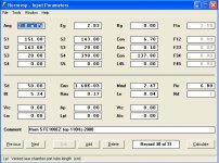
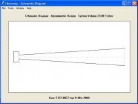
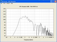
And number 2:
How are you getting this? In 2pi space sims, the mouth is normally facing forward and on the same plane as the driver, so a '0' offset is used since the path-length difference is acoustically the [close enough] same for the intended gain BW, which calcs a way different [and more plausible IME] summed response.
GM
xrk971
Hello,
please show us the membran movement of your simulation,
and compair it with the driver data, Xmax 0,28 mm.
http://www.fostexinternational.com/docs/speaker_components/pdf/fe108ez.pdf
before you try an 48 db active solution at 150 Hz, try another driver.
Hello,
please show us the membran movement of your simulation,
and compair it with the driver data, Xmax 0,28 mm.
http://www.fostexinternational.com/docs/speaker_components/pdf/fe108ez.pdf
before you try an 48 db active solution at 150 Hz, try another driver.
Hi HM,
We all know where this is going.(from the fh3 thread)... 😉 I forgot that the OP was using a 280 micrometer stroke driver! You are right, it's going to go nonlinear to get down to 80 Hz. I did not run the sim, just commenting on the freq response curve.
We all know where this is going.(from the fh3 thread)... 😉 I forgot that the OP was using a 280 micrometer stroke driver! You are right, it's going to go nonlinear to get down to 80 Hz. I did not run the sim, just commenting on the freq response curve.
In the Swan horn/TL designed for this driver, it has no problem playing into the ~60Hz range (at very moderate volumes) and is a really nice-sounding driver (no sharp peaks). Fostex specs have been off by an order of magnitude at times.
A minor point pertinent to hm & xrk's discussion:
What do you mean by Xmax? How do you define it? There are many different methods of putting a value to it. All of them are different, with different criteria, and they usually end up providing different figures to each other. For those who don't know much about the subject, here's a few illustrations of the realities of the situation.
-Some manufacturers set Xmax as the point at which a drive unit reaches 10% THD. Which would be fine, except for the fact that it pays no attention to the distortion figures above or below this point. The driver could be at 9.999% THD for a couple of mm of travel before it reaches the 10% threshold defined as Xmax. Anyone think 9.999% THD will sound significantly better than 10% THD? No, I don't either. You might say this is unlikely. Possibly it is. The point is, you don't know unless you measure it yourself. Beyond this excursion point, so the theory goes, THD will increase. No question of that; it will. But how quickly? It depends on the design of the motor. Some will more swiftly than others. And we haven't even considered at this point the fact that THD itself doesn't mean much; it's just a factor; the sum of all the distortion components present. But it is the individual distortion components that count. 3rd order is usually more noticable than 2nd order. Higher orders are usually more objectionable than either of these. And so on & so forth.
-There are other means of specifying Xmax. One of these is to simply subtract the height of the VC winding from that of the magnetic gap. No distortion value is specified with this method.
-Another method is to take the absolute value of the height of the magnetic gap minus the height of the VC winding and divide this by 2. Once again, no distortion value is specified with this method.
-It is quite possible to take a drive unit, calculate a value for Xmax using the three example methods I have outlined above (there are others too), and end up with three completely different figures.
Xmax is a nebulous concept until you state the criteria you have used to define it. Most manufacturers do not do this, so comparisons are not possible or indeed logical until you have ascertained they used the same method, or you measure the units yourself and set Xmax using a consistent approach. Even when you have done so, it won't necessarily mean much.
Last edited:
cool down,
i think there exist a few standards and DIN Norm so the best way is to make a measurement, compair and listen, but the membran movement would be interesting,
show us some.
i think there exist a few standards and DIN Norm so the best way is to make a measurement, compair and listen, but the membran movement would be interesting,
show us some.
- Status
- Not open for further replies.
- Home
- Loudspeakers
- Full Range
- Horn sensitivity question