I have a meter out an old tape deck that was used as a vu meter. Well I scrapped the deck and kept the meter. I want to know if there is any way to hook it up to my current amp so that it will serv as a sound meter. I just want a visualation not a actual vu meter. Could I hook it up through the speaker outs and use somekind of transistor so is wont peak out when I turn it up past a point? Can I hook it up through the preamp with a regular transistor that will max when the amp is maxed? I have a fair amount of knowlage when it comes to electronics but with no formal training I dont know near as much as people on here do. For a 15 year old kid I know a whole lot about this stuff and want to become an electronic engineer and/or mechanical engineer so I want to learn as much stuff as I can. Can anybody point me in the right direction for books and/or web sites where I can learn this stuff? If you wanted to know this is going to be in an Allied 495 Reciever.
> a meter out an old tape deck that was used as a vu meter.
Probably not a real VU meter, unless you scrapped an Ampex. No matter, the cheap semi-VU meters are fun too.
First question: is it AC or DC? Put a 1K resistor in series, and then clip it across your speaker. Play soft, turn up slow. If it is AC, it will bounce-up with the music. If it is DC, it will sit at the left peg, quivering on bass notes.
If it is DC, add a rectifier. The simplest is to use any bridge rectifier, like you use in power supplies. 1Amp is more than plenty. 50V is OK up to very high powers, but 100V or more is a wise idea. The + and - bridge outputs go to the meter; the "AC" rectifier pins are the new AC inputs. Now try with the series resistor. If it wants to move left of the left pin, reverse the + and - connections. (Meter cases are often unmarked, and sometimes marked wrong.)
If AC (or DC plus the rectifier), fiddle the resistor so the needle slams the right peg when playing as loud as you ever need. 5K or 10K might be a good guess. Then you should have a nice bounce for most medium and loud levels. Getting a straight meter to read very low levels is actually very tough work.
A small refinement is to use Germanium diodes instead of Silicon rectifiers. Lower forward voltage drop, better twitch on low levels. Schottky rectifiers are also low-drop, though not as low as Germanium (at these low currents). The classic true-VU meter used copper-oxide, but you don't find these very often any more.
If this solves anything I have hooked a led in parallel with a potentiometer before that on one of the poles and that worked but if I wasnt constanly ajusting the knob for the potentiometer I would end up overpowering the led. If I dont hook the led in I dont get a good bounce. This meter is out of an old sharp tape deck. It has 2 meters for left and right channle. Is there a way for me to have the circuit at a certain voltage with out manualy having to change the resistance?
Jasmeleg said:....I have a meter out an old tape deck that was used as a vu meter. Well I scrapped the deck and kept the meter. I want to know if there is any way to hook it up to my current amp so that it will serv as a sound meter.....
http://sound.westhost.com/project55.htm
Or you can try this..
http://www1.int.conrad.com/scripts/...ext_ztab=&area=115010&page=2&price=No+price!#
http://www1.int.conrad.com/scripts/...ext_ztab=&area=115010&page=2&price=No+price!#
the cheap semi-VU meters are fun too.
Thanks for not judging...😀
I put a meter on my amp 'cause it looked cool (I guess the same reason manufacturers do it...)
So far I am planning to switch between voltage input, (the power supplies for ea. channel are separate and have a variac) temp of heatsinks, and now VU ish dancin' needles.
I have contacted Elliott in the past and after apologizing for my shallowness, I asked how to make a bad VU. He basically said what you did, but you were more clear. He also said the germanium diodes really help, and that if you are using a voltmeter without any built in resistor, use LOTs of resistance while experimenting, because the are quite fragile.
I have a VU meter circuit here. It's somewhat more complicated than the simple recifier approach, but the diode forward voltage is exactly compensated for, so it works even with very low input levels.
Since it's something pretty you want to look at, you might also be interested in the fading LED driver that is on the same page.
Since it's something pretty you want to look at, you might also be interested in the fading LED driver that is on the same page.
Variac said:Ooooooooo...led thingy
The LM3915/3916 bargraphs are well-suited to simple meters on the line output, as the basic 1.2V scale can be re-jigged to suit anything from around 0.4V to over 2V levels with a couple of trimpots.
They'll also take an AC audio signal without rectification -- the input to the buffer opamp has an internal (schottky?) diode fitted (anode to ground) so negative-going inputs are limited to the low drop.
You could do a similar trick with your analogue meter and use an opamp as buffer on the line signal so (a) volume adjustments don't affect the needle movement and (b) it provides a high impedance input to the meter so sound quality to the amp isn't affected.
Back in the 70's I used to contract design to an australian broadcast mixer manufacturer (all the ABC mixers,etc..) - they used REAL VU meters where the rise and fall and overshoot characteristics were rigorously specified.
Then along came all the amps featuring VU meters labelled for power output to fill a front panel. Then LED bargraphs. I saw value in that for the PA so included a 10 LED bargraph with top LED clipping indicator and the market loved it. In the '70's. Then any visual embellishment was considered a distraction from the music, at least for Hi End.
Everything old is new again.
Greg
Precision rectifier
Has anyone thought about using a precision rectifier for VU metering? Wouldn't that be quite an effective and inexpensive solution if you are concerned about the forward voltage drop on a diode? You can also control the gain as well as time constant of a precision rectifier very easily.
In its simpliest form, it is just an opamp, a couple resistors and a couple diodes. Why make it unnecessarily complicated?
I believe most half decent engineering books mention precision rectifiers.
Re: Precision rectifier
The circuit I posted is a precision rectifier. Maybe not the same as the ones you see normally and maybe not the simplest or best way of doing it, but it is one nonetheless.tlf9999 said:Has anyone thought about using a precision rectifier for VU metering?..
Ok you guys have me lost. Can someone please explain how to do this using words and not just diagrams. I can look up words and see what you are saying but diagrams I can read them but not fluientley.
My Evil: I am sorry that I didn't check yours out in greater detail. The first schematic has some interesting things. However, I am not sure if XX1A does anything other than adding a diode forward drop on its input. That I guess is what you were trying to achieve as the voltage rise is then offset by D3.
XX1B and D4 almost formed a precision rectifier, except the diode is out of the feedback loop.
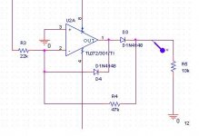
Here is what you will typically see out of a textbook and in reality.
R3/R4 and D3 follow the feedback loop for opamp U2A. an A/c source is applied on R3. During the negative cycle, current is flowing U2A's output, through D3 and then R4 to create a positive voltage on R5. The output voltage depends on just the current going through r3 and the value of R4, and has nothing to do with the the forward voltage drop of D4.
D3 is there to provide a discharge for current going through R3 during the positive cycle.
As you can tell, the output is just half wave. You can create full-wave rectification by suming the input signal with the output of this precision rectifier. But it makes no sense to do this for the purpose of VU metering.
XX1B and D4 almost formed a precision rectifier, except the diode is out of the feedback loop.
Here is what you will typically see out of a textbook and in reality.
R3/R4 and D3 follow the feedback loop for opamp U2A. an A/c source is applied on R3. During the negative cycle, current is flowing U2A's output, through D3 and then R4 to create a positive voltage on R5. The output voltage depends on just the current going through r3 and the value of R4, and has nothing to do with the the forward voltage drop of D4.
D3 is there to provide a discharge for current going through R3 during the positive cycle.
As you can tell, the output is just half wave. You can create full-wave rectification by suming the input signal with the output of this precision rectifier. But it makes no sense to do this for the purpose of VU metering.
Attachments
- Status
- Not open for further replies.
- Home
- Amplifiers
- Solid State
- Hooking up VU meter?