Hi
I have built myself a Vibratone-like cabinet, from the internal leslie unit from a boring 80´s hammond organ. There is now a new and powerfull 10 inch eminence speaker in the cabinet, and a slow motor and a fast motor.
1st question:
I know the old vibratone units had a crossover of some sort, but is this really nescessary? The eminence speaker can handle 75 watts, and None of my amps are over 60 watts? Maybe the crossover is essential when it comes to the tone, or was it originally put in there to protect small speakers?
2nd question
The switching from fast to slow must be done by a relay, so I can avoid high voltage in a footswitch!
I found this drawing somewhere:
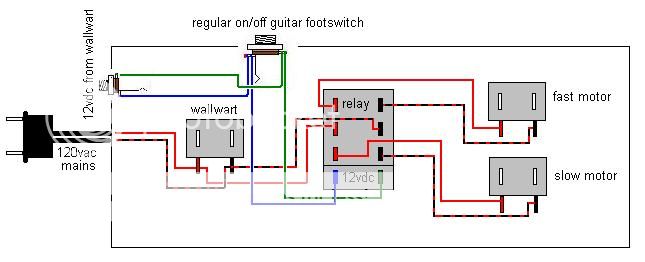
Would this work? Noisy maybe, but could this be sorted out using some capacitors?
I´ve made several tube amps from scratch, so I know my way around hihg voltage and safety, but must admit that I´ve never even heard of a relay before, so this is unknown territory for me?
Best regards
_Kasper
I have built myself a Vibratone-like cabinet, from the internal leslie unit from a boring 80´s hammond organ. There is now a new and powerfull 10 inch eminence speaker in the cabinet, and a slow motor and a fast motor.
1st question:
I know the old vibratone units had a crossover of some sort, but is this really nescessary? The eminence speaker can handle 75 watts, and None of my amps are over 60 watts? Maybe the crossover is essential when it comes to the tone, or was it originally put in there to protect small speakers?
2nd question
The switching from fast to slow must be done by a relay, so I can avoid high voltage in a footswitch!
I found this drawing somewhere:
Would this work? Noisy maybe, but could this be sorted out using some capacitors?
I´ve made several tube amps from scratch, so I know my way around hihg voltage and safety, but must admit that I´ve never even heard of a relay before, so this is unknown territory for me?
Best regards
_Kasper
The crossover is for the horn. I would not eliminate it unless you are bi amping and going active.
For motor switching, you will need a DPDT relay. The diagram you show will work. It doesn't show an additional switch to cut power altogether to the motors for no effect. You can add that.
For motor switching, you will need a DPDT relay. The diagram you show will work. It doesn't show an additional switch to cut power altogether to the motors for no effect. You can add that.
Thanks for the reply
I don´t think there were any horns int the vibratone units. Only a 10inch or 12inch speaker, and a rotating styrofoam-thingy? But still, I´m shure there were a crossover cirquit in there somewhere...?
I don´t think there were any horns int the vibratone units. Only a 10inch or 12inch speaker, and a rotating styrofoam-thingy? But still, I´m shure there were a crossover cirquit in there somewhere...?
So you have a single speaker in a box, with a whirly thingie in front of the speaker? Then you don;t need a crossover. A crossover limits the freq range to a driver. One would not want low end going to a horn driver for example. But if you have only one speaker you don;t need it. And especially a guitar speaker which has limited range to start with.
Think of your relay as a DPDT toggle switch. COuld you wire one of those for your two motors? If sso, the relay is nothing more than a switch with a magnet coil to move it. Energize the magnet coil it switchyes to one state. Remove power from the voil, it revrets back to the other state.
Your drawing works only if the relay you chose has the common poles in the center. A lot of relays have the common on the end instead.
A 12v wall wart can probably power the relay, but the way you have drawn the diagram, the footswitch is ACROSS the wall wart supply. That means when you step on teh switch it shorts out your wall wart. That would turn the relay off, but probably also kill the wall wart. Your footswitch should be in series with the relay.
The Vibratones and Leslie 16 and 18 models didn't have horns but they did have crossovers. I have forgotten exactly how they worked, I think they were intended to run the mids to the vibratone and pass the highs and lows to other speakers. Most guitarist never used them and prefer to have the full range go thru the leslie.
I have tried to sketch it up myself....sorry, I know it´s a small image
Is this what you mean?
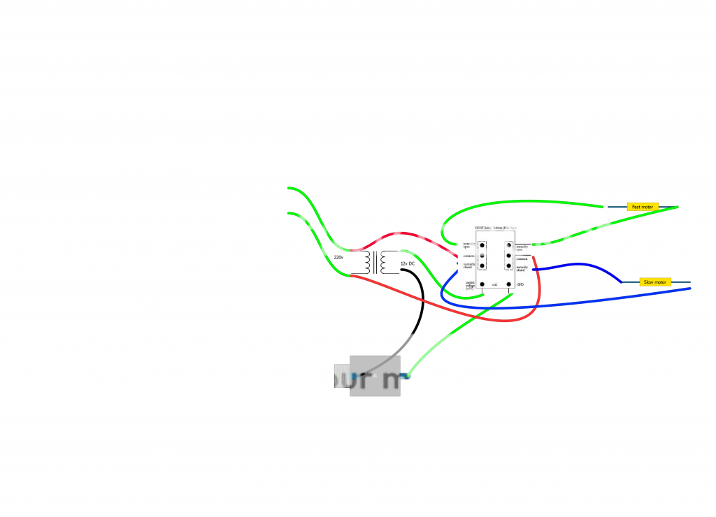
And where would the capacitors go to quiet the switching down?
Is this what you mean?
And where would the capacitors go to quiet the switching down?
When i rebuild leslie´s for standalone use i install 2 SS relays in the cabinet with a small PCB transformer and bridge.
Stompbox with 2 DPDT switches.
First start/stop and second corale/tremolo.
The SS relays cost some money but the work like a charm and are dead quiet.
To find a foot switch that doesn´t make a loud katchunk when switched is another quest 😀.
Stompbox with 2 DPDT switches.
First start/stop and second corale/tremolo.
The SS relays cost some money but the work like a charm and are dead quiet.
To find a foot switch that doesn´t make a loud katchunk when switched is another quest 😀.
When i rebuild leslie´s for standalone use i install 2 SS relays in the cabinet with a small PCB transformer and bridge.
Stompbox with 2 DPDT switches.
First start/stop and second corale/tremolo.
The SS relays cost some money but the work like a charm and are dead quiet.
To find a foot switch that doesn´t make a loud katchunk when switched is another quest 😀.
how would these two DPDT switches be wired to a TRS jack to achieve the start/stop chorale/tremolo control for SS relays??
- Status
- Not open for further replies.
- Home
- Live Sound
- Instruments and Amps
- Homemade Leslie cabinet