Oh, and the voltage on the 120Ohm resistor is 7.4Volts, with the pin-2s grounded. This resistor is responsible for creating a continous current, right? Because i saw lots of circuits, and as i know, this resistor can be replaced by an LM317 in a so-called "current generator" mode.
Last edited:
Maybe the 27nF 400V capacitors are faulty before the EL84...? It's looks like that this amp amplifies the hum from the PSU? Is this possible?
Greetings from FixitLand!
Just back from lunch...
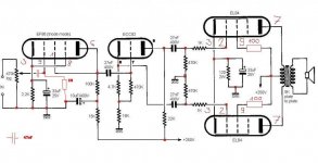
OKeh. First, we have 7.4 V across the 120-ohm resistor, for total cathode current of 61.67 mA. That's fine for two EL84s. Very good, too, that the audio fell silent when you grounded pin 2. That clears the power supply. We now look toward the previous stage, the phase splitter. You likely have a fair amount of hum 'cuz the PI tube isn't there, but we had to be sure. Put the PI tube back in. Before firing the set up, we need to look at this circuit. It's a bootstrapped cathodyne. The term "bootstrapped" refers to the bias resistor (R5, 470K) returning not to ground but to a point in the cathode circuit. The effective resistance of R5 is greatly increased. (Just why that is can wait 'till later, or you can Google "bootstrapped amplifier" to learn more.)
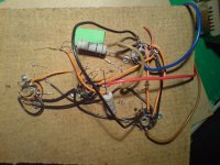
Now looking at your build photo. The phase-inverter tube (1/2 of a 12AU7 or ECC82) appears to be wired correctly, except for its heater. As noted previously, this tube should have pins 4 and 5 connected to one leg of the heater supply and pin 9 connected to the other leg, if being run from 6.3 V. Make those connections now, then try again. (Don't forget to remove the grounds from the EL84 grids...<grin!>) You may or may not have hum/buzz. If hum is present, DO NOT try grounding the ECC82 grid! Instead, temporarily connect a 0.1-uF 200 V (or better) capacitor from pin 2 to ground. The set should be pretty much dead-silent at that point. Measuring the voltage from pin 2 to ground should give a reading of about 1/3 to 1/4 the B+, and you may hear some hum/buzz when doing that measurement. If that's the case, so far so good! Let us know the results.
Incidentally, using only half of the ECC82 isn't terrific but you can do it. A better choice would be to acquire a 6C4 single triode (or use the other half of the ECC82 in a stereo setup). Another possibility, since you're triode-strapping the EF86, might be to use an ECC81 (12AT7) as voltage amp and cathodyne, or even an ECF82 (6U8) triode/pentode combo tube. Either of those options would save you one tube socket. That's for later, perhaps.
Take care,
--
J. E. Knox "The Victor Freak"
Just back from lunch...
OKeh. First, we have 7.4 V across the 120-ohm resistor, for total cathode current of 61.67 mA. That's fine for two EL84s. Very good, too, that the audio fell silent when you grounded pin 2. That clears the power supply. We now look toward the previous stage, the phase splitter. You likely have a fair amount of hum 'cuz the PI tube isn't there, but we had to be sure. Put the PI tube back in. Before firing the set up, we need to look at this circuit. It's a bootstrapped cathodyne. The term "bootstrapped" refers to the bias resistor (R5, 470K) returning not to ground but to a point in the cathode circuit. The effective resistance of R5 is greatly increased. (Just why that is can wait 'till later, or you can Google "bootstrapped amplifier" to learn more.)
Now looking at your build photo. The phase-inverter tube (1/2 of a 12AU7 or ECC82) appears to be wired correctly, except for its heater. As noted previously, this tube should have pins 4 and 5 connected to one leg of the heater supply and pin 9 connected to the other leg, if being run from 6.3 V. Make those connections now, then try again. (Don't forget to remove the grounds from the EL84 grids...<grin!>) You may or may not have hum/buzz. If hum is present, DO NOT try grounding the ECC82 grid! Instead, temporarily connect a 0.1-uF 200 V (or better) capacitor from pin 2 to ground. The set should be pretty much dead-silent at that point. Measuring the voltage from pin 2 to ground should give a reading of about 1/3 to 1/4 the B+, and you may hear some hum/buzz when doing that measurement. If that's the case, so far so good! Let us know the results.
Incidentally, using only half of the ECC82 isn't terrific but you can do it. A better choice would be to acquire a 6C4 single triode (or use the other half of the ECC82 in a stereo setup). Another possibility, since you're triode-strapping the EF86, might be to use an ECC81 (12AT7) as voltage amp and cathodyne, or even an ECF82 (6U8) triode/pentode combo tube. Either of those options would save you one tube socket. That's for later, perhaps.
Take care,
--
J. E. Knox "The Victor Freak"
Greetings from FixitLand!
They're probably not faulty. With so much of the circuit open-circuited (tubes not present), the "loose ends" of the circuit act as antennae, picking up all kinds of noise. The power supply is in close proximity and radiates a strong field at harmonics (multiples) of the power frequency. When you add in the phase-inverter circuit, we'll know more about the state of the 27 nF caps. One thing about those...that value is rather low in this circuit; usually it's more like 47 or 100 nF. The only bad effect will be a bass rolloff higher than usual; you'll still hear sound.
Take care,
--
J. E. Knox "The Victor Freak"
Maybe the 27nF 400V capacitors are faulty before the EL84...? It's looks like that this amp amplifies the hum from the PSU? Is this possible?
They're probably not faulty. With so much of the circuit open-circuited (tubes not present), the "loose ends" of the circuit act as antennae, picking up all kinds of noise. The power supply is in close proximity and radiates a strong field at harmonics (multiples) of the power frequency. When you add in the phase-inverter circuit, we'll know more about the state of the 27 nF caps. One thing about those...that value is rather low in this circuit; usually it's more like 47 or 100 nF. The only bad effect will be a bass rolloff higher than usual; you'll still hear sound.
Take care,
--
J. E. Knox "The Victor Freak"
Greetings from FixitLand!
I meant to mention: The EL84 grids in this circuit are at DC ground potential, so there's no shock hazard in touching them. But it's VERY good to be leery of putting your hand near 250 VDC (or even an eighth of that), so no worries there! Learn to respect, but not fear, electricity. (If you fear, you avoid. Can't have fun with tubes when you're avoiding them! <grin>) Never touch a circuit with both hands. Know the parts of the circuit where you are working.
Take care,
--
J. E. Knox "The Victor Freak"
Well, i don't want to touch anything, because 250Volts creeps the hell out of me. 😀 ...
I meant to mention: The EL84 grids in this circuit are at DC ground potential, so there's no shock hazard in touching them. But it's VERY good to be leery of putting your hand near 250 VDC (or even an eighth of that), so no worries there! Learn to respect, but not fear, electricity. (If you fear, you avoid. Can't have fun with tubes when you're avoiding them! <grin>) Never touch a circuit with both hands. Know the parts of the circuit where you are working.
Take care,
--
J. E. Knox "The Victor Freak"
Greetings from FixitLand!
Just back from lunch...
OKeh. First, we have 7.4 V across the 120-ohm resistor, for total cathode current of 61.67 mA. That's fine for two EL84s. Very good, too, that the audio fell silent when you grounded pin 2. That clears the power supply. We now look toward the previous stage, the phase splitter. You likely have a fair amount of hum 'cuz the PI tube isn't there, but we had to be sure. Put the PI tube back in. Before firing the set up, we need to look at this circuit. It's a bootstrapped cathodyne. The term "bootstrapped" refers to the bias resistor (R5, 470K) returning not to ground but to a point in the cathode circuit. The effective resistance of R5 is greatly increased. (Just why that is can wait 'till later, or you can Google "bootstrapped amplifier" to learn more.)
Now looking at your build photo. The phase-inverter tube (1/2 of a 12AU7 or ECC82) appears to be wired correctly, except for its heater. As noted previously, this tube should have pins 4 and 5 connected to one leg of the heater supply and pin 9 connected to the other leg, if being run from 6.3 V. Make those connections now, then try again. (Don't forget to remove the grounds from the EL84 grids...<grin!>) You may or may not have hum/buzz. If hum is present, DO NOT try grounding the ECC82 grid! Instead, temporarily connect a 0.1-uF 200 V (or better) capacitor from pin 2 to ground. The set should be pretty much dead-silent at that point. Measuring the voltage from pin 2 to ground should give a reading of about 1/3 to 1/4 the B+, and you may hear some hum/buzz when doing that measurement. If that's the case, so far so good! Let us know the results.
Incidentally, using only half of the ECC82 isn't terrific but you can do it. A better choice would be to acquire a 6C4 single triode (or use the other half of the ECC82 in a stereo setup). Another possibility, since you're triode-strapping the EF86, might be to use an ECC81 (12AT7) as voltage amp and cathodyne, or even an ECF82 (6U8) triode/pentode combo tube. Either of those options would save you one tube socket. That's for later, perhaps.
Take care,
--
J. E. Knox "The Victor Freak"
Good morning! (at least, the time is 9am here 😛 )
So, i disconnected the grounding wire from the EF84s, put the ECC82 back. I still hear a buzz, but it's much quieter now with the ECC82. I measured the voltage at the EL84s pin2 to ground, it's 0 Volts. But if i mesure the pin2 - B+ voltage, it's 210Volts.
Last edited:
Oh, and i connected the capacitor to the pin2 - GND, it's 0.1uF 630V MKP. The buzz is less, i think it's coming from the PSU. Just like when i grounded the EL84s pin2 without the ECC82.
More info. I replaced the capacitors, and put the EF86 back in. When i measure the voltage between it's anode and the ground, i can hear clicking noise. But when i'm trying to measure the voltage between the pin 9 and the B+, i CAN'T hear any clicking. Maybe the EF86 is faulty?
I found a bug. 😀 The EF86s cathode resistor (2.2k) wasn't connected. 🙂) Amateur... In a vacuum tube, electrons are flowing from the cathode to the anode...
Congrats  , now how about upgrading your cardboard to a nice pine breadboard, you know you want to................😎
, now how about upgrading your cardboard to a nice pine breadboard, you know you want to................😎Greetings from FixitLand!
Back from my day off, and I hear --
Cool beans! That's good progress. (Did you remove the temporary capacitor on the grid of the ECC82?)
What sort of distortion are you hearing? Can you adjust the volume level, and if so, does that change the distortion?
You heard a buzz even with the ECC82 grid bypassed. Could you please measure the DC voltage from the ECC82 plate (pin 1) to ground, and from its cathode (pin 3) to ground?
Another thought: With the set powered off, use your ohmmeter to check each ground point against one another. A bad ground point might be a hum/buzz source. Connect one lead of the meter to the power-supply ground, and the other to each circuit ground point (low end of R13/C6, junction of R9/R10, low end of R6, low end of R1/R2/C1, and even the input ground). Each should show a very low resistance. If you find one with a higher resistance, you may have found the hum culprit. Strap the ground points with wire.
There's light at the end of the tunnel...
Take care,
--
J. E. Knox "The Victor Freak"
Back from my day off, and I hear --
YEEES YEEES, my amp is working! 😀 It's distorted, and the volume is VERY low, but OMG. 🙂
Cool beans! That's good progress. (Did you remove the temporary capacitor on the grid of the ECC82?)
What sort of distortion are you hearing? Can you adjust the volume level, and if so, does that change the distortion?
You heard a buzz even with the ECC82 grid bypassed. Could you please measure the DC voltage from the ECC82 plate (pin 1) to ground, and from its cathode (pin 3) to ground?
Another thought: With the set powered off, use your ohmmeter to check each ground point against one another. A bad ground point might be a hum/buzz source. Connect one lead of the meter to the power-supply ground, and the other to each circuit ground point (low end of R13/C6, junction of R9/R10, low end of R6, low end of R1/R2/C1, and even the input ground). Each should show a very low resistance. If you find one with a higher resistance, you may have found the hum culprit. Strap the ground points with wire.
There's light at the end of the tunnel...
Take care,
--
J. E. Knox "The Victor Freak"
Greetings from FixitLand!
Just had another wild-hair thought: When you grounded the EL84 grids, you got silence, but when you installed the ECC82 phase splitter and bypassed its grid, you still got buzz. I wonder if the EL84s might be oscillating. Try temporarily disconnecting C6, the 33-uF electrolytic. (That cap is rather small...would prefer a 220-uF unit.) Removing the cap will reduce the stage gain. You may hear less buzz, or NO buzz. Let me know.
Take care,
--
J. E. Knox "The Victor Freak"
Greetings from FixitLand!
Dang. I STILL forgot to ask: What are you using for a signal source?
Take care,
--
J. E. Knox "The Victor Freak"
Dang. I STILL forgot to ask: What are you using for a signal source?
Take care,
--
J. E. Knox "The Victor Freak"
News. 🙂 I disassembed the shitty cardboard, and made a whole new amp. I picked up a wooden board, and built the amp on it. The results are amazing. VERY loud sound, much much lower distortion. But i still hear the buzz. It's not my psu, 'cuz if i ground the EL84s pin2, there i no hum at all... Any thoughts? Maybe i need to put a capacitor to the 22kOhm and the 18+4.7kOhm...?
Greetings from FixitLand!
Dang. I STILL forgot to ask: What are you using for a signal source?
Take care,
--
J. E. Knox "The Victor Freak"
My MacBook Pro, and my phone. I know, it's not the best...
Greetings from FixitLand!
There are two changes in that schematic: 100-ohm resistors have been added in series with the EL84 screens. That's cool. The other change is a coupling capacitor (value unspecified, but 47 nF or 100 nF are fine) and a 1M grid leak resistor added at the EF86 grid. That's cool too; it removes the threat of the direct-coupled volume control going "open-wiper" and removing the tube's grid leak. But at this point, don't worry much about these mods. Neither are likely to help the buzz problem much.
Take care,
--
J. E. Knox "The Victor Freak"
Oh, and what dou you think about that? Some friends at the hobbielektronika.hu mentioned this.
There are two changes in that schematic: 100-ohm resistors have been added in series with the EL84 screens. That's cool. The other change is a coupling capacitor (value unspecified, but 47 nF or 100 nF are fine) and a 1M grid leak resistor added at the EF86 grid. That's cool too; it removes the threat of the direct-coupled volume control going "open-wiper" and removing the tube's grid leak. But at this point, don't worry much about these mods. Neither are likely to help the buzz problem much.
Take care,
--
J. E. Knox "The Victor Freak"
Greetings from FixitLand!
Back from my day off, and I hear --
Cool beans! That's good progress. (Did you remove the temporary capacitor on the grid of the ECC82?)
What sort of distortion are you hearing? Can you adjust the volume level, and if so, does that change the distortion?
You heard a buzz even with the ECC82 grid bypassed. Could you please measure the DC voltage from the ECC82 plate (pin 1) to ground, and from its cathode (pin 3) to ground?
Another thought: With the set powered off, use your ohmmeter to check each ground point against one another. A bad ground point might be a hum/buzz source. Connect one lead of the meter to the power-supply ground, and the other to each circuit ground point (low end of R13/C6, junction of R9/R10, low end of R6, low end of R1/R2/C1, and even the input ground). Each should show a very low resistance. If you find one with a higher resistance, you may have found the hum culprit. Strap the ground points with wire.
There's light at the end of the tunnel...
Take care,
--
J. E. Knox "The Victor Freak"
ECC82 pin1-GND: 147Volts
pin3-gnd: 67Volts
I measured each ground point, 0.1, or 0.2Ohms.
Last edited:
- Status
- Not open for further replies.
- Home
- Amplifiers
- Tubes / Valves
- Homemade EL84 Push-Pull amp doesn't work