found a cool homebrew high voltage supply, looks like from the 40's. very crude, completely unregulated, but i'm just looking for something to give me B+ for prototyping tube preamps for guitar, so it suits my needs, and i really enjoy working with such an old basic circuit. i'm looking to restore it, and am hoping for a little guidance and help in evaluating and improving the circuit. i don't want to complicate it much and i'm not interested in any regulation, i just want to make adjustments for better component longevity and reliability, avoiding oscillation etc.
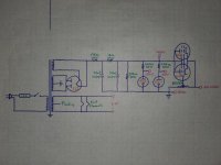
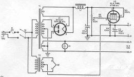
the colourful schematic is how it's hooked up currently. i've also attached the schematic of a similar power supply taken from a 1963 magazine, that i found on another thread on this site (https://www.diyaudio.com/community/threads/simple-variable-tube-power-supply.96995/), for reference and improvement ideas.
at bare minimum i plan on installing a 3 prong cord, replacing the can cap with some axials, and replacing the potentiometer as it measures 180K but should be 50K. all resistors are fat ohmite wirewounds that measure perfectly on spec. tubes are a pair of 6L6 as the pass tubes, a super handsome 5Z3 rectifier, an 0D3 and a 0C3. gonna test em and replace if needed, making sure i have reasonably matched 6L6.
in terms of operation principles, i don't know much about bench power suppy design and would like to have a good ground-up understanding. it seems the large 50K pot acting as the cathode resistor for the 6L6's, combined with the fact that the plates are tied directly to the B+, allows the cathode to approach the B+ voltage? i don't understand how there can be much if any conduction across the tube if the cathode and plate are at the same potential. it seems the pass tubes are meant to operate at low current consumption until an external load is connected?
worst conditions for the pot are dropping 400V across 50K, allowing 8mA through, dissipating 3.2W. i'd like to replace it with a 10W for a nice safety margin, but unfortunately mouser and digikey only have 2W versions. they do, however, have 25K 5W's, so i'm considering one of those in series with a 5W 22K or 27K resistor on the ground side, settling for a smaller voltage range of perhaps 250V-400V, which would still suit my purposes just fine.
but i'm wondering if the biasing setup from the 1963 magazine would be preferable in any way, where the cathode uses the same proportionate resistance to ground (100K since it's only for one 6L6), and the grid voltage is instead tapped directly from the B+. does one configuration to source the grid voltage offer an advantage over the other? the only advantage i can see is that a 100K pot will only dissipate 1.6W when dropping 400V, but the same suppliers only offer up to 2W pots at that resistance, so i'd still be stuck at the same impasse. unless this value is non-critical, in which case i could use a 250K 2W.
the filament center tap was left floating, which i'm assuming is so that the filament is free to follow the cathode to keep from exceeding the 6L6's Vhk max rating of 180V. but, wouldn't this leave the 6.3V filament output terminals floating at up to 400V DC?! of course, tying the center tap to the 6L6 cathodes like in the other schematic would do the same thing, but that's why they have a separate 6.3V transformer for those terminals... thinking i'll tie the center tap to the 6L6 cathodes so it has a reference, and just not use the 6.3V output terminals. any issue having the indicator bulb floating at up to 400V though?
adding C2 from the 1963 schematic onto the output seems like it can't hurt even with my current setup, same with adding 100R screen stoppers. the 10K grid stopper seems like a great idea too, but not sure if it would affect bias if i stick with the current biasing method?