smoking-amp said:"If the empty core bobbin is a "C", you won't need anything
fancy to wind the copper through the donut hole.
The problem with C cores is that they don't have the low leakage L of a toroid to get the huge bandwidths.
Not a C core, just an empty C bobbin. For externally winding the
copper on the outside, and later internal spooling of the helical
iron core. No more absurd than anything else in this thread.
Obviously has to be some Teflon washers or whatever, for the
trapped bobbin to be turned... And an access gap through the
active copper windings, I don't know if that gap counts as a "C".
Packing the core in tight enough not to vibrate will be about
impossible, must assume the final step would then be potting.
I'm not attempting to be practical, just feeding the loons.
There was a technic called "potato transfo" by here, forgotten now I suppose.
The copper wire was wound on a cylindric bobbin, then many steel wires was passed thru and bend so that they roughly join.
You know why they was so named 😀
Yves.
The copper wire was wound on a cylindric bobbin, then many steel wires was passed thru and bend so that they roughly join.
You know why they was so named 😀
Yves.
"could we revert to the standard circular shuttle and just make the shuttle cross-section small enough that it doesn't take up much more space"
Sure. I just think the Potthoff C design is a lot easier to make than the rotating shuttle designs. Take a look at all those guide wheels and bearings on the Jovil heads posted earlier. I am going to call Jovil to see if their shuttle bobbins and heads are available separately soon too. At least the bobbins might be affordable.
"an empty C bobbin. For externally winding the
copper on the outside, and later internal spooling of the helical
iron core."
This could be attempted, sure. Would need something like the mylar ribbon shuttle that Jovil has. But this would not get the metal wound up very tight this way. But then a little slack in the metal windup would lower the effective Mu some, so DC balance would not be such a problem for P-P. 1 mil thick permalloy tape would work great in a ribbon shuttle. (Hmmm...., on second thought, the Jovil ribbon shuttle bends the ribbon 180 deg. around a small roller. So that's NG. But, see my "deranged" version of this above, no 180 deg. bend using a belt drive on the outside of the ribbon stack. )
But why bother. There are R cores already. These are wound up cores with a circular cross section. Two round R bobbins each clip together over the circular cross section straight sections. These have a molded in gear sprocket on one end of the bobbin. You just use a gear drive to spin the bobbin on the core to wind the wire on. Result is a gapless toroid with two C core like bobbins on it.
An even simpler way would be to just use four sets of I laminations, interleave-stacked as a square, with winding bobbins over each one. This would get a little nearer to a toroid for leakage L than just two bobbins. Nothing special required at all.
But if you already just happen to have a toroid winder sitting on the bench... well...., its easier than any of these.
Don
"There was a technic called "potato transfo" by here, forgotten now I suppose."
Sounds like this could work for SE with a huge effective air gap. Probably looked like a potato with roots sticking out. I'll bet it makes a lot of noise though with audio thru it.
Maybe re-arrange kenpeter's version to make a coil assembly shaped like a toroid, then use a toroid winder to wrap magnetic wire around it. Could call it the hairy smoking donut.
Don
"Full manual approach ... for the fun. ....."
Looks like they used some type of bicycle rim for the shuttle there.
We need something like about 8 or 9 inches in diameter by 1/2 to 3/4 inch square cross section U shape. I've been trying to think of some common thing that fits the shape. Only thing I can think of would be some old IBM mini 9 track tape reel. How about some kind of dispenser reel for string, fishing line .... laundry line pulley, I guess a big pulley could be bored out in a lathe, but once we bring a lathe into this for machining, almost anything could be made from scratch anyway.
So is the whole idea of this thread to DIY a toroid winder, or is anyone exploring buying one used or new? How much are the small, low volume toroid winders anyway? Are they that much that DITY makes sense?
Rgs, JLH
Rgs, JLH
"So is the whole idea of this thread to DIY a toroid winder, or is anyone exploring buying one used or new? "
Well, the thread was inspired by the Potthoff patent as an easy way to build one. But any solution to toroid winding is fair game here. I have not been able to find a used toroid winder on Ebay so far, but I think there was some mention of a used one in some link for around $8000.
I just checked with Jovil manufacturing on new prices for progressive wind capable setups, and unless you've got BAILOUT access, probably not under consideration here:
For doing 5 inch max diameter coil winds, their model SMC-2 with a 9 inch winding head goes for $24,000. The 9 inch head alone for $7500. The bobbin alone for $700, the little tiny slider on the bobbin goes for $60.
A Chinese made version, the SMC-2E with a 9 inch head and lower quality is available for $15,750.
A cheaper model, the SMC-1E, (Chinese) with a 7 inch head (max. 3 inch coil diameter winds) is available for $13,500. The 7 inch head alone for $2500, bobbin alone for $400. (SMC-1E does not handle 9 inch heads or bigger though)
They said they will sell less than a whole machine, so you could buy a head or just a bobbin:
9 inch: $7500 / $700 or 7 inch: $2500/$400
I have priced the Teflon scrap on Ebay for building a bare bones Potthoff at around $100. But this requires further machining to build one. Probably a few hundred $ spent at a machine shop, unless you have a lathe or milling machine handy. (I do) Since Teflon is easy to machine, another option is a rotary table bolted on a drill press base, with a router head and a milling cutter. The big risk here is that one may have to do some experimenting and multiple tries before they get it right (spill-off friction/spill-over radius, spill-off wire capture across the C gap, friction in the loop-accumulator .....) The Potthoff patent is not a Heath Kit instruction manual.
One likely will also want to make some variants of the Potthoff for different belt widths. This would just mean an extra Teflon piece for the bottom of the belt groove and another cog belt. And some smaller cog-belt sprockets. A smaller width version would allow one to wind interstage xfmrs too.
Don
Or one could go to Wall-Mart and buy a 26" bicycle rim.
A cloth covered hair scrunchie to prevent the wire from
coming off the wheel all at once. But that would be too
easy...
If you need a machine to spin it, Legos... and/or a rock
tumbler.
A cloth covered hair scrunchie to prevent the wire from
coming off the wheel all at once. But that would be too
easy...
If you need a machine to spin it, Legos... and/or a rock
tumbler.
"If you need a machine to spin it, Legos... and/or a rock
tumbler."
Mount the wheel horizontally thru the toroid above a flat table. Tie some cheese on a string from the wheel that dangles just above the table surface. Then tie a leash on a mouse and attach that to the wheel a few inches from the cheese. If its a really big toroid, you could attach a cat about a foot behind the mouse. High speed mode then.
Or just train some monkey to hand wind them for peanuts.
Horizontally above a flat table of that slick cutting board stuff.
Now you are almost talking realistic.
Simpler answer to all the cat'n'mouse drive, patent search
"Rube Goldberg". Perhaps then you can save a part or two,
starting with string cheese.
Now you are almost talking realistic.
Simpler answer to all the cat'n'mouse drive, patent search
"Rube Goldberg". Perhaps then you can save a part or two,
starting with string cheese.
smoking-amp,
Wow I had no idea the small Jovil winder were that much. That more than justifies going DIY if possible.
This is the kind of pricing that drives me nuts. You know they only have 1/10 of that amount in the machine. They price it based on how much a full production coil winder could make with it. I just hate that because there are so many different transformers I would like to have wound, but I can't find a shop to do it for me.
If something doable comes out of this thread, it would be great.
Rgs, JLH
Well, the problem with all the forementioned methods is how to
control the slack. And I have the beginnings of an idea, but not
yet the complete workable solution.
I envision a bicycle brake cable sleeve, flexible but not too much...
We don't want the wire inside to be getting kinked. Some sort of
a thingamabobber (not sure how this works yet) rides around the
rim dragging this sleeve behind like a tail. The rim itself need not
be directly driven, but pulled around by the tension of wire being
transferred.
"I envision a bicycle brake cable sleeve......."
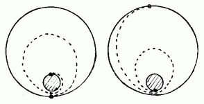
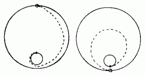
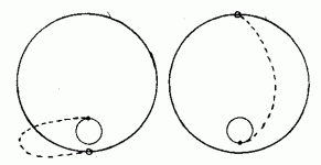
We've been thinking along the same lines. I was thinking of a roll of Teflon tubing dragged along by the wheel. I was thinking that with a multi-turn spiral of TFE tubing, the length of wire in it does not change much as the spill-off point on a big wheel rotates around from near to far side. I guess either a short or long "brake cable/TFE tube" maintains constant length. The short one will have to flex a lot between the near and far side and might get out of convenient diameter range (or require sharp bending periodically) for passing thru the toroid hole. The long one can just squeeze the spiral back and forth some, but will take up more space with multiple tube turns going thru the toroid hole simultaneously.
Maybe just go for one full turn of hose/sleeve spiral.
Don
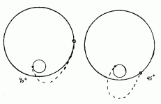
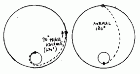
Here's the 1/2 turn again at 45 degrees and 90 degrees. Looks like 45 degrees has a clearance problem getting thru the core.
So far I have kept the rotation speeds of the two ends of the cable synchronous. We COULD allow the rotation speed of the bobbin feeding end to speed up (or phase advance) when the loop gets unwieldy, then slow back down again (phase retard) when max stretchout is needed. (Winding the excess cable around the core momentarily)
So far I have kept the rotation speeds of the two ends of the cable synchronous. We COULD allow the rotation speed of the bobbin feeding end to speed up (or phase advance) when the loop gets unwieldy, then slow back down again (phase retard) when max stretchout is needed. (Winding the excess cable around the core momentarily)
Attachments
Phase shifting or advancing 1/2 turn version:
Having the shuttle end pull on the cable as Kenpeter suggested may be sufficient to do the same thing for phase advancing. Since it would be pulling on the cable, it would naturally wind up excess cable on the core when excess is available. But it might also snag the cable tightly around the core then too. That could be problematic with a square cornered core cross section. Especially since the wire tension needs to be higher then to pull the wire down tight.
Having the shuttle end pull on the cable as Kenpeter suggested may be sufficient to do the same thing for phase advancing. Since it would be pulling on the cable, it would naturally wind up excess cable on the core when excess is available. But it might also snag the cable tightly around the core then too. That could be problematic with a square cornered core cross section. Especially since the wire tension needs to be higher then to pull the wire down tight.
Attachments
Kenpeter,
Seems to me that the dragged 1/2 turn sleeve is now doing about the same motion as the friction plate/slack accumulator did before with the wire. Ie, the wire is conforming to the same shape during a rotation. So how about putting the sleeve thru a friction plate. The wire would pull thru the sleeve and the sleeve pulls sideways mostly thru the friction plate. That might keep the sleeve off the toroid surface then if it is shortened further. Maybe shorten it by 1/2 a circumference around the toroid cross section.
edit:
duh, on second thought, that probably isn't working, since the wire won't be dragging after leaving the sleeve.
Don
The idea of phase advancing the bobbin feeding end I think is not going to work. The two sleeve ends still have to pass each other during each rotation at some point. The excess sleeve will end up all wound up on the core at that point.
Seems that for the cases of the wire pulling the sleeve around, one will need a sleeve with variable stiffness along its length. It should be stiff near the bobbin end and more flexible toward the toroid end. A constant torque spiral resulting with at least one turn (like in post # 35 I think).
Next idea:
The Jovil gear heads wind the excess wire slack back up on the bobbin during each cycle by moving the spill-point around (ahead) independently from the wire bundle. Two separate drives (bobbin and spill-off) are used.
Thinking Teflon tubing again, how about putting slit TFE tubing over the edge of the bobbin and provinding a separate belt drive for moving it around, maybe could even use the gap in the tubing ends as the spill point. Maybe just put slit TFE tubing over both edges of the bobbin, then a timing belt riding on top of both tube edges. Rubber rollers on the bottom side of the bobbin power the bobbin independently.
At least some of the Jovil gear heads just use friction to control the spill-point. We would drive the bobbin using the bottom rollers with an optional friction dragging belt on the TFE tube edges. When the wire goes slack, it quits pulling the tube edge slot along and the wire pulls back into the bobbin instead until it tightens up again. Then starts pulling the the slot along again.
Only thing I don't like about this scheme is it seems to bend and stretch the H-ll out of the wire. So any way we could fix this up? Otherwise, microprocessor controlled speed control on the slot control belt drive too.
Even the dual controlled setup bends the wire badly. Since the wire path is now a 90 degree spoke from the bobbin down to the toroid. Maybe a short piece of springy sleeve tangential to the bobbin could provide a gradual bend for the wire, while bending out of the way when passing the toroid closely.
Back to Potthoff:
The slit TFE tubing for spool edges gives me an idea for making the Potthoff cheaper. Just use metal side plates (still a Teflon bottom for the belt to ride on) to form the C. (grease the belt edges) Then the slit TFE tubing goes over one of the plate edges to form the wire spill over edge (maybe glued on somehow). The TFE tubing could even have it ends bridge the gap in the C by going thru the toroid with a small cylinder piece stuck in the tubing ends to join them. That way the re-capture of the wire spill-over is avoided too, it just slides along merrily thru the gap on the tubing. Looking tuff to beat now.
Don
- Status
- Not open for further replies.
- Home
- Amplifiers
- Tubes / Valves
- Holy Smoking Toroid Winder
