I just wasn't sure why it was not preferred for valves.
I'm not saying that it was wrong, but it might just an opinion from someone who did the star grounding wrong.
I've built dozens of Hi-Fi projects and about 10 guitar amps, all of which have no problem at all with hum. Tubes vs transistors shouldn't make any difference when it comes to grounding, except that it's better to tie a center tap of the filament winding to the star center gnd. If the winding doesn't have a center tap, you can effectively create one using resistors (1kohms should work fine).
I tie the earth ground (green) wire of the AC line cord to the chassis right where it comes in, rather than directly to the star center (bolt). That worked better in one amp I built. I tie the pwr tranny secondary center tap to the neg. side of the filter caps, and then run a wire from there to the "star center" gnd. That way the high current pulses charging the large filter caps won't modulate the rest of the grounds nearly as much.
I tie together grounds in a given stage, and run one wire from that to the star center. I put a .01uF 3kV ceramic cap across both the primary and secondary of the power tranny. In the primary, the concern is Rf energy coming in on the AC line cord. On the secondary, the issue is the rectifier diodes making noise when they switch on and off at the zero volts crossing. I also put .01uF 3kV caps across the main filter caps to effectively bypass their inductance at high frequencies.
The star center must tie to the chassis in only one place (or you create a gnd loop), at which point the chassis becomes a "Faraday Cage", which shields the innerds from Rf energy in the air. All connectors must be isolated from the chassis, unless you are choosing that one location to tie the star center to the chassis (I don't). All filament wiring is done with solid strand twisted pair wiring, which is kept away from all other wiring. The twisting causes the electromagnetic fields to largely cancel out.
Another thing to know is that single ended stages have very poor power supply rejection of hum, so filtering of the B+ need to be significant. I usually use two sections of RC, with roughly 50 ohms feeding 100uF per section. That's for the output stage, and a bit more for the earlier stages.
I also put a passive Rf filter at the audio input (a 10K R feeding a 220pF to gnd for -3dB at 17kHZ, if the source Z of the guitar is 10k ohms (it's usually between 5K and 10K ohms)), to reduce Rf energy coming in there. The guitar makes a pretty good antenna otherwise. Rf coming in there will get "detected" by the circuit, creating intermodulation sum and difference energies, the difference energies can cause noise in the audio frequency range.
I hope this helps.
Last edited:
Since no one has mentioned a ground bus, I will promote that method, which is my preferred method of grounding. First a lot of vintage units from the golden age of audio use a ground bus so it is a widely accepted method. I use the mounting bolt of the power transformer or some point close to it for the start of the ground bus. I use at least a 14 awg or larger solid copper wire that is conveniently located across the tube sockets. It usually anchors at the opposite end of the chassis but is insulated at that point. With this method all the resistors and caps are grounded directly to the ground bus. To me it is easier to be sure each component is properly grounded since you can easily examine each solder joint along the ground bus. I have never had any hum issues ever, when using a ground bus. cheers, 808
Here is an example, from my amp prototype.
You see a PCB where all power supplies end, 800V for B+, 400V for driver, 270V for screen grids, +12V for filaments, and -70V for bias. All outputs of all sources are connected such a way so traces from corresponding capacitors are the shortest. It is the "Zero reference point". All power supply currents close in this point, and you see a bunch of black wires going there, including ground wire from chassis and power outlet. As the result the amp is silent as in a grave. The main point is, no high and low current chains share any common wire that can cause coupling through the wire's resistance and inductance. Ground loop in such case don't hurt since they don't carry dirty currents.
You see a PCB where all power supplies end, 800V for B+, 400V for driver, 270V for screen grids, +12V for filaments, and -70V for bias. All outputs of all sources are connected such a way so traces from corresponding capacitors are the shortest. It is the "Zero reference point". All power supply currents close in this point, and you see a bunch of black wires going there, including ground wire from chassis and power outlet. As the result the amp is silent as in a grave. The main point is, no high and low current chains share any common wire that can cause coupling through the wire's resistance and inductance. Ground loop in such case don't hurt since they don't carry dirty currents.
Attachments
I always build with a single bolt grounded star onto the chassis, and this bolt then tied to safety earth. My systems run extremely sensitive speakers of +100db drivers. I do point to point and pay only slight attention to cable routine (they usually look like a spaghetti mess). I run AC heaters but always use tightly twisted pairs.
None of my builds hum in the slightest - not even a tiny trace. Take that how you will but I would never build any project that didn't implement star grounding.
Shoog
I do exactly the same and also have no problems. I put the chassis point close to the mains transformer.
My builds underneath are not a thing of beauty, but they don't hum!
It depends on what you mean by "approached sensibly" and "good result". Newbies tend to put all ground connections to the star 'point', so inject PSU charging pulses and then wonder why they get buzz. Certainly star grounding can be used mindlessly to get a tolerable result, which may be better than a bad result. Better still to understand grounding.Shoog said:The problem with this response is that star grounding approached sensibly is just about the easiest and most consistent way for a novice builder to achieve a hum free project. It requires less experience to get a good result.
This is the key to low noise grounding, yet it is surprisingly often ignored.Bob Richards said:I tie the pwr tranny secondary center tap to the neg. side of the filter caps, and then run a wire from there to the "star center" gnd. That way the high current pulses charging the large filter caps won't modulate the rest of the grounds nearly as much.
I mentioned a ground bus. I even said that any real 'star' is actually a short bus.DAK808 said:Since no one has mentioned a ground bus
It depends on what you mean by "approached sensibly" and "good result". Newbies tend to put all ground connections to the star 'point', so inject PSU charging pulses and then wonder why they get buzz. Certainly star grounding can be used mindlessly to get a tolerable result, which may be better than a bad result. Better still to understand grounding.
Whenever I have helped any novice to fault find a humming project, it has always boiled down to starting out applying a star ground and then irrationally diverging from the approach. Correct the divergence and the hum magically goes away. As I said, if applied sensibly and consistently it has "never" failed to get a good/excellent result in mine (and obviously many others) experience.
Shoog
I even said that any real 'star' is actually a short bus.
As I said, if applied sensibly and consistently it has "never" failed to get a good/excellent result
So, star grounding is a valid concept, and everyone is actually applying it in all hum-free amplifiers. Knowing when to "deviate" from the rules of thumb is what requires deeper knowledge, as DF96 has mentioned.
Graduated star grounds is a more flexible approach which is well discussed in that Valve Wizard article. What I do is half way between a single star ground and a graduated star ground.
Shoog
Shoog
This was also one of my responses.This is the key to low noise grounding, yet it is surprisingly often ignored. This is what I am used to, but I hear people complaining of hum that got me thinking.
I mentioned a ground bus. I even said that any real 'star' is actually a short bus.
But pretty much finished on the design now, just waiting for parts. For a headphone amp you will or I hope will be impressed.
The guitar practice amp i am currently working up started out with a "star". I replaced that with a length of 14ga copper last night as a bus.
Much neater, less power supply noise.
.:Sent by pneumatic tubes
Much neater, less power supply noise.
.:Sent by pneumatic tubes
The guitar practice amp i am currently working up started out with a "star". I replaced that with a length of 14ga copper last night as a bus.
Much neater, less power supply noise.
.:Sent by pneumatic tubes
Very neat with some perfectly straight 14ga. Think I am maybe mixing my self with guitar and "Hi-Fi" two different things, oh well design is pretty much done. Just need to order the tannies.
Complete overkill for a headphone amp, but I like the extra headroom when the mood fancies
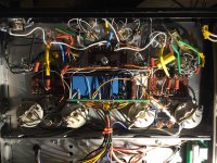
Before:

Star ground or ground spaghetti monster?
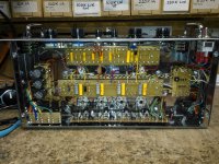
After:

There are a few other changes, like cleaned up tone stack / gain control wiring. And the big honkin 1R resistor. And the heater wiring for the 9 pin socket not only exists but has a switch to toggle between 12ax7 and 6n2p.
Star ground or ground spaghetti monster?
After:
There are a few other changes, like cleaned up tone stack / gain control wiring. And the big honkin 1R resistor. And the heater wiring for the 9 pin socket not only exists but has a switch to toggle between 12ax7 and 6n2p.
Before:
Star ground or ground spaghetti monster?
After:
There are a few other changes, like cleaned up tone stack / gain control wiring. And the big honkin 1R resistor. And the heater wiring for the 9 pin socket not only exists but has a switch to toggle between 12ax7 and 6n2p.
That is bad for my OCD lol. But if you like the sound who am I to judge.
Oh yeah beautiful it is not. I have some regrets about my choice of enclosure. It's a gift for a little girl who bought her first strat a few months ago.
You must be joking.🙄The current that causes problems with solid state amplifiers are with respect to ground. Valve amplifiers have an output transformer, so no high current to worry about. Use twisted pair for heater wiring and centre tap to ground.
In an SS amp, the "big" ground current is speaker current return to ground.
In a Tube amp, the "big" ground current is speaker current return to ground.
Say you are driving a 4 ohm speaker with 100W RMS, the "- speaker terminal will "send" 5A RMS to ground, *both* in the SS and in the Tube amps, exactly the same.
In fact, situation is slightly worse in Tube amps, because cathode current comes from/through ground, while Power Transistors receive their current from + and - rails.
You must be joking.🙄
In an SS amp, the "big" ground current is speaker current return to ground.
In a Tube amp, the "big" ground current is speaker current return to ground.
At least the output transformer of tube amps, "separates" the amp's ground and the ground of the circuit driving it.
An amp, with input shorted, has no hum problem. Then the amp is connected with the source/pre and there is music flowing. The music hinders the ability to hear that there is now hum problem 😀
Its vital you keep currents in successive stages away from each other or you will introduce noise.
Noise in the power supply can also be a factor.
I always use multiple decoupling for each stage of the amp.
Its vital charging impulses into smoothing capacitors don't modulate the audio ground or you will get hum.
I once designed a USB mixer and didn't bother star grounding it.
I got 1 volt peak to peak of hum on the output with a grounded input !
The smoothing capacitors charging impulses were shifting the ground up and down and modulating the audio signal.
A careful revision of the pcb separating the power supply from the audio circuit fixed it.
- Status
- Not open for further replies.
- Home
- Amplifiers
- Tubes / Valves
- Hmmmm Star ground