Thanks for sharing. I'm wondering about the places you omitted or modified the circuit from a classic blameless amp? In particular these:
1. lack of current mirror regen resistors
2. lack of LTP degen resistors.
3. lack of Darlington VAS
4. lack of driver cross coupling
5. lack of two pole compensation
6. independent CCS for LTP and VAS
7. Diode string vs vbe multiplier
8. lack of small series resistance to work with C1 for RFI
9. high gain (48, ~6dB more than typical)
10. lack of current limit protection
11. lack of a Baker clamp(s) on the VAS
12. lack of LTP cascode, and some might ask about a VAS cascode
13. lack of a 3EF vs 2EF
Of course, some of these features are of little or zero advantage, so I'm just listing them because some people think they are important even if I don't. There are a few more that I didn't list because I think them bad ideas like a symmetric IPS. I completely understand that simple is an important feature, and free of exotic parts.
I think worrying about slow VAS transistors is a bit pointless since the compensation makes it much slower than even a MJE340. A very fast VAS transistor can oscillate with trace inductance alone, so a slower transistor could avoid some headaches.
Remember LTC spice is free and a wonderful tool too try ideas without the expense of blown transistors. There is a thread here in DIYA if you need help, and plenty of youtube videos. And it is easy to test conditions in spice that reveal behavioral issues and how to avoid them. Of course, you need to be aware of the real-world limitations of simulations.
Thanks For Sharing Your Experience With Us Just Print it Out and Try To building this Amp..I mounted and calibrated it this weekend. The sound is very nice, well distributed in bass, mid and treble. The current from the VAS is enough for a good performance and allows the transistors to run very cold.
It's worth built and listening to.
See the amplifier first run video:
HM100X FIRST RUN - YouTube
Attachments
Erm, its definitely not a Darlington, I think you mean the emitter-follower VAS? Not the same thing and its crucial for performance the first EF transistor has no signal swing on its collector as the whole point is to cancel out the effect of the VAS's Cbc on the input stage. The EF transistor simply buffers the input stage to isolate it from non-linear currents flowing through the Cbc (Miller capacitance) of the final VAS transistor. Its the large signal swing that leads to non-linear Cbc.3. lack of Darlington VAS
If you used a Darlington you'd see non-linear Cbc currents directly in the first transistor.

So What You Think About This Amp???Erm, its definitely not a Darlington, I think you mean the emitter-follower VAS? Not the same thing and its crucial for performance the first EF transistor has no signal swing on its collector as the whole point is to cancel out the effect of the VAS's Cbc on the input stage. The EF transistor simply buffers the input stage to isolate it from non-linear currents flowing through the Cbc (Miller capacitance) of the final VAS transistor. Its the large signal swing that leads to non-linear Cbc.
If you used a Darlington you'd see non-linear Cbc currents directly in the first transistor.
Dear djpaulinho07 Can I Use 1n5400 Diodes For D6 Or D7???? Or Why You Write (Invert) With Bd139 / BD140 Any Details About it?Hello friends...
Here in Brazil we have a very active diy audio community and due to research I am bringing a new circuit for your enjoyment.
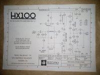
It is a simple audio amplifier, polarized with diodes, with an option for ground suspension of the input signal, 100W, full CCS and differential current mirror
Around here in Brazil we have a lot of bad circuits that are shared on the web that leave DIY people very frustrated when they set up and it doesn't work, so whenever I can I share new tried and tested ideas.
Here are some data measured on a bench
Power: 100W @ 4 Ohm
Sensitivity: 380mV
Input Impedance: 47kOhm
Frequency Response: 10Hz~191KHz @ 3dB
Damping Factor: 995
Simulated THD: 0.02% @ 1KHz (real life measurement will happen soon)
Schematic:

PCB:

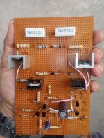
Prototype PCB:

SCHEMATIC UPDATED: 08/17/21
🙂 I am a happy DipTrace user🙂
I have recently build this amp and burn out by giving + - 55v supply..
or is this just a guitar amplifier????
or is this just a guitar amplifier????
Dear djpaulinho07 I have built this amp 2nd time and Now it is ready for testing can't wait more for testing it..Hello friends...
Here in Brazil we have a very active diy audio community and due to research I am bringing a new circuit for your enjoyment.
It is a simple audio amplifier, polarized with diodes, with an option for ground suspension of the input signal, 100W, full CCS and differential current mirror
Around here in Brazil we have a lot of bad circuits that are shared on the web that leave DIY people very frustrated when they set up and it doesn't work, so whenever I can I share new tried and tested ideas.
Here are some data measured on a bench
Power: 100W @ 4 Ohm
Sensitivity: 380mV
Input Impedance: 47kOhm
Frequency Response: 10Hz~191KHz @ 3dB
Damping Factor: 995
Simulated THD: 0.02% @ 1KHz (real life measurement will happen soon)
Schematic:
PCB:
Prototype PCB:
SCHEMATIC UPDATED: 08/17/21
🙂 I am a happy DipTrace user🙂
I decided to built it on zero PCB so I did it. I hope it works well 😊
I used in4007 instead of 1n4148 is that okay?
Thanks for sharing have a nice day..
Attachments
Well its a shame the feedback take-off point was moved to a worse location in the PCB revision...So What You Think About This Amp???
After build I have test this amp with
-+48v DC and it works very well sound quality is op also bass treble is so clear I am happy it works very well for me without bias adjusting. 😎 again thanks for sharing it with us..
-+48v DC and it works very well sound quality is op also bass treble is so clear I am happy it works very well for me without bias adjusting. 😎 again thanks for sharing it with us..
- Home
- Amplifiers
- Solid State
- HM100X - Simple 100W power amplifier BR