The deuce is back on the bench. Its been probably a year since I've last touched it, so I have to commend myself for a first job done fairly well and the reliability of this amp not given optimal conditions and my partial rebuild (about 2 years ago).
Now I am having some strange issues and its going a little over my head.
I have two different rail voltages at V1 and V4 (12BY7A). V4 is running about 460v and V1 is running about 180v on the plates.
The AC balance adjustment (internal) has never worked properly. I can't find a thing wrong with the wiring of that circuit and Ive looked over it atleast a dozen times now.
I have 20ohm 2w bias resistors on the cathode per Jim McShane's recommendation on his site. I have blown out 2 of them, and a 3rd one looks like it has been running hot (discoloration in the middle). Only one of them has never given me an ounce of trouble and still looks normal.
This is a partially rebuilt unit... All of the caps have been replaced except for some of the ceramic discs. I have replaced several resistors on the turret boards to replace those that have gone out of acceptable value.
Any ideas?
thanks in advance
The deuce is back on the bench. Its been probably a year since I've last touched it, so I have to commend myself for a first job done fairly well and the reliability of this amp not given optimal conditions and my partial rebuild (about 2 years ago).
Now I am having some strange issues and its going a little over my head.
I have two different rail voltages at V1 and V4 (12BY7A). V4 is running about 460v and V1 is running about 180v on the plates.
The AC balance adjustment (internal) has never worked properly. I can't find a thing wrong with the wiring of that circuit and Ive looked over it at least a dozen times now.
I have 20ohm 2w bias resistors on the cathode per Jim McShane's recommendation on his site. I have blown out 2 of them, and a 3rd one looks like it has been running hot (discoloration in the middle). Only one of them has never given me an ounce of trouble and still looks normal.
This is a partially rebuilt unit... All of the caps have been replaced except for some of the ceramic discs. I have replaced several resistors on the turret boards to replace those that have gone out of acceptable value.
Any ideas?
thanks in advance
Let's start with the V1/V4 plate voltages - 180 volts is about right, the 460 volts is way off. The most likely cause is there is no current flowing through V4, which means you won't have any voltage drop across R39 or R41. Try swapping a known good tube into V4 and see if that doesn't fix the voltage issue. But before you do measure the resistance from V4 pin 1 to ground. It should be about 220 Ohms. And be sure the heater voltage is about 5 volts (not 6, 5 - there are 2 dropping resistors in the heater supply).
Next, the AC balance - how do you know it isn't working properly? As I've mentioned many times before, that little internal meter is WAY overmatched trying to read the AC balance. If you are assuming that because the meter hardly moves or doesn't move at all that the AC bias is not functioning - you can't make that assumption. Look at the AC balance with a dual trace scope - one probe to each tube in the channel and you can see the waveform change as you turn the pot. BTW, if the AC balance pots are original I'd replace them - they get pretty corroded inside.
The cathode resistors are blowing/running hot because the tubes are running away - or at least well over the proper cathode current. It could be the tubes themselves - or it could be the tubes are losing bias from any number of causes from bad pin to socket contact to bad bias supply issues to intermittent failure of the bias winding in the power trafo. IMHO the proper repair now is to (pardon the "plug" but it's needed to reply properly) install the bias upgrade kit I offer which replaces the stock power trafo bias winding, totally rebuild the bias circuit - caps, rectifier, etc., and replace or properly retension the octal sockets. When you replace the sockets replace the 270 Ohm screen resistors and install 18 Ohm or 20 Ohm 2 watt cathode resistors. I use 18 Ohms for the good KT-88s or 6550s, for some tubes 20 Ohms is a better idea.
Here's the bottom line - there really is no place for an operating Citation II that isn't completely rebuilt anymore. The YOUNGEST Cit II in the world was built 50 years ago, some are as old as 55! If your power supply is original it's shot - even if it "works", it is working at a fraction of its capability. The bias supply is suspect, the tube sockets are suspect, the resistors are out of spec or physically deteriorating. And the audio path caps all need to be new, those old ceramic discs have no place in there - and good coupling caps are a must! The original RCA females are steel and are corroded and shot in the vast majority of cases. The speaker terminals are in the same shape. The bias pots need to be CAREFULLY disassembled, cleaned, and rehabilitated. The old PVC wiring insulation is likely to be crisp, and corroded under some of the insulation. We recommend every electrical component in the amp be replaced or reconditioned except the magnetics and one or two other pieces.
The Cit II ran VERY warm under the chassis. So in case you are tempted to think that an amp shouldn't need all this stuff - the facts are that they do. The amp is like a sports car - it requires more maintenance and repair to work properly than a family sedan. However, by properly applying carefully chosen new parts with some updating and minor but important modifications the amp can be VERY reliable for many years to come.
If you don't totally rebuild the Cit II it's not a matter IF it will fail, but WHEN it will fail. I think you've run into some of that now. My bench tech Don Sachs and I have done HUNDREDS of these amps - we know from experience.
Let me know what questions you have and I'll do my best to help. If you'd rather do it off forum drop me a note.
Thanks for your reply Jim, you helped me with the original rebuild way back when. I know of your experience, and it goes without question. Was just a matter of time, budget, and patience when I first started this project so I didn't get it 100% done.
Here's what I've done so far.
I have already tried swapping a few different tubes into V1/V4 to no effect.
The meter balances correctly until I apply the 60hz signal from the heater supply (rear RCA). When I connect the lead, the meter bounces around like CRAZY!!!! You can hear it buzzing around and smacking the extremes of the housing. It simply won't be still no matter what extreme I turn the balance pots. It does this with 2 different set of tubes (set of Winged C's and the orig HK coke bottles, all test good). I measured the bias supply under the 60hz load... V9 raised to 6.4v and V10 went to 3.3v. As for AC balance, I can do a manual balance to within 200mv or so with a multimeter, I just worry that something internally is wrong to make the meter behave this way.
My power trans has a bad bias winding so I am already using a separate transformer for bias supply. EVERYTHING on the power supply end is fresh, modernized components except for the choke.
The only capacitors that haven't been replaced is the ceramic discs on the turret board. All of the polyester film and electrolytics have all been replaced, all inspired by your work when I did the orig. rebuild. Will be replacing the V1/V4 decoupling caps with .1 tonight. (so there's one less old disc on the turret boards)
All of the socket resistors on the power tubes have been replaced. (270ohm to UL taps and 20ohm bias) The only remaining original resistors/caps are on the bottom of the turret board, and I have checked them all - in spec. The ones that have gone out of spec have been replaced. I have ordered replacement discs for the rest. As much as I detest the idea I think I'm gonna replace the sockets tonight. (God help me)
Was wondering if anybody has drawn up a schematic to mod the power supply to isolate the channels after the choke? Wouldn't mind doing this while I have it torn apart. I have 2 500v 470uF caps on hand, I thought they would make a lovely addition along with the mod but I can't seem to find much information about it floating around the web.
Last edited:
Thanks for your reply Jim, you helped me with the original rebuild way back when. I know of your experience, and it goes without question. Was just a matter of time, budget, and patience when I first started this project so I didn't get it 100% done.
Here's what I've done so far.
I have already tried swapping a few different tubes into V1/V4 to no effect.
The meter balances correctly until I apply the 60hz signal from the heater supply (rear RCA). When I connect the lead, the meter bounces around like CRAZY!!!! You can hear it buzzing around and smacking the extremes of the housing. It simply won't be still no matter what extreme I turn the balance pots. It does this with 2 different set of tubes (set of Winged C's and the orig HK coke bottles, all test good). I measured the bias supply under the 60hz load... V9 raised to 6.4v and V10 went to 3.3v. As for AC balance, I can do a manual balance to within 200mv or so with a multimeter, I just worry that something internally is wrong to make the meter behave this way.
My power trans has a bad bias winding so I am already using a separate transformer for bias supply. EVERYTHING on the power supply end is fresh, modernized components except for the choke.
The only capacitors that haven't been replaced is the ceramic discs on the turret board. All of the polyester film and electrolytics have all been replaced, all inspired by your work when I did the orig. rebuild. Will be replacing the V1/V4 decoupling caps with .1 tonight. (so there's one less old disc on the turret boards)
All of the socket resistors on the power tubes have been replaced. (270ohm to UL taps and 20ohm bias) The only remaining original resistors/caps are on the bottom of the turret board, and I have checked them all - in spec. The ones that have gone out of spec have been replaced. I have ordered replacement discs for the rest. As much as I detest the idea I think I'm gonna replace the sockets tonight. (God help me)
Was wondering if anybody has drawn up a schematic to mod the power supply to isolate the channels after the choke? Wouldn't mind doing this while I have it torn apart. I have 2 500v 470uF caps on hand, I thought they would make a lovely addition along with the mod but I can't seem to find much information about it floating around the web.
Okay, here we go -
Will be replacing the V1/V4 decoupling caps with .1 tonight. (so there's one less old disc on the turret boards)
There are no .1 disc decoupling caps anywhere in a Citation II. The decoupling caps are C2a and C2b, and they were originally a 50/50 uf 450 volt dual section can. I'm not sure what cap you are describing.
IMPORTANT! You have at least one very serious issue - the reason the meter is behaving the way it does is because the amp is oscillating. That indicates not only a serious malfunction, it will destroy stuff if allowed to continue!!
I measured the bias supply under the 60hz load... V9 raised to 6.4v and V10 went to 3.3v.
No offense meant, but I have no idea what you are talking about here. First off, bias measurements are always made with no signal applied. Second, there is no place in the bias supply where you would find 6.4 or 3.3 volts - AC or DC.
And the voltage issue on V4? You could measure the voltage from one end of R39 or R41 to the other end - unless there is voltage drop across the resistor there is no current flowing. But...
You must find the cause of the oscillation and stop it from occurring. If that has been occurring for a while then you now know what is destroying your resistors The Cit II circuit is inherently stable - so for it to be oscillating there is something seriously wrong. I STRONGLY recommend you do no more anything to the amp until it's stable. Right now it's a time bomb! The output tubes are likely damaged at this point. But don't put new tubes in until the oscillation stops. If the amp only oscillates when the AC balance test is being made I'll be surprised - it is likely doing it with any signal applied - but you can't see it since the meter is turned off.
There are so many places to look for the cause of an oscillation... but since the amp doesn't do it normally I'd suggest looking for wiring errors, bad components, etc. first. This troubleshooting can be done with the amp off.
If you can't find the problem with the amp off I suggest you get professional help. You could spend a lot of money and do a lot of damage trying to sort things out. Again no offense meant - but this is probably outside your skill set to straighten out. If you want I can put you in touch with Don Sachs, but that's your call.
BTW, all the resistor references I made were from the H-K original schematic, not the SAMS.
Last edited:
I know my skill set isn't quite up to yours or Don's, but I intend to get caught up to it at some point. I never will if I send it off to the pro's for help. I would argue that you and Don didn't acquire your skill set by dropping your gear off with someone, and the only way I learn is by diving in.
The V9/V10 voltages were taken from the cathode, before the 20ohm resistor. (where you would measure bias voltage with a VM) This is where I found the 6.4 and 3.3v, and that was with a signal applied. Maybe an irrelevant test since there was a signal applied, cathode voltage probably should increase under the circumstances.
V4 pin 1 to ground 210ohms, V1 pin1 to ground 216ohms. Seems normal.
The meter only spazzes out when I plug in the ac balance signal. Otherwise, cool and calm - will balance easily.
From your site:
"(2) .1uf/630 volt polypropylene film & foil bypass caps for V1/V4 decoupling."
in the level 2 upgrades. I could only assume you meant the .001 ceramic C3/C19.
I NEVER trust Sam's schematics! They screwed me over on my Fisher 400C in about 5 different places. All references are to the original HK schematics from the assembly manual.
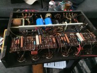
btw that 12K (right corner of the picture) is still in spec but I have already ordered a replacement. Cant believe I didn't have 12K on hand!
The V9/V10 voltages were taken from the cathode, before the 20ohm resistor. (where you would measure bias voltage with a VM) This is where I found the 6.4 and 3.3v, and that was with a signal applied. Maybe an irrelevant test since there was a signal applied, cathode voltage probably should increase under the circumstances.
V4 pin 1 to ground 210ohms, V1 pin1 to ground 216ohms. Seems normal.
The meter only spazzes out when I plug in the ac balance signal. Otherwise, cool and calm - will balance easily.
From your site:
"(2) .1uf/630 volt polypropylene film & foil bypass caps for V1/V4 decoupling."
in the level 2 upgrades. I could only assume you meant the .001 ceramic C3/C19.
I NEVER trust Sam's schematics! They screwed me over on my Fisher 400C in about 5 different places. All references are to the original HK schematics from the assembly manual.
btw that 12K (right corner of the picture) is still in spec but I have already ordered a replacement. Cant believe I didn't have 12K on hand!
Attachments
Last edited:
I know my skill set isn't quite up to yours or Don's, but I intend to get caught up to it at some point. I never will if I send it off to the pro's for help. I would argue that you and Don didn't acquire your skill set by dropping your gear off with someone, and the only way I learn is by diving in.
The V9/V10 voltages were taken from the cathode, before the 20ohm resistor. (where you would measure bias voltage with a VM) This is where I found the 6.4 and 3.3v, and that was with a signal applied. Maybe an irrelevant test since there was a signal applied, cathode voltage probably should increase under the circumstances.
V4 pin 1 to ground 210ohms, V1 pin1 to ground 216ohms. Seems normal.
The meter only spazzes out when I plug in the ac balance signal. Otherwise, cool and calm - will balance easily.
From your site:
"(2) .1uf/630 volt polypropylene film & foil bypass caps for V1/V4 decoupling."
in the level 2 upgrades. I could only assume you meant the .001 ceramic C3/C19.
I NEVER trust Sam's schematics! They screwed me over on my Fisher 400C in about 5 different places. All references are to the original HK schematics from the assembly manual.
btw that 12K (right corner of the picture) is still in spec but I have already ordered a replacement. Cant believe I didn't have 12K on hand!
The V9/V10 voltages were taken from the cathode, before the 20ohm resistor. (where you would measure bias voltage with a VM) This is where I found the 6.4 and 3.3v, and that was with a signal applied.
The V9 and V10 voltages were at the cathodes? If what the meter read was anywhere near accurate that means V9 was passing 320 ma (yikes!!) and V10 was passing 165 ma. In turn that means the tubes were trying to dissipate 144 watts for V9 and about 74 watts for V10. Those are both WAY over spec. Those tubes are almost undoubtedly toast.
The meter only spazzes out when I plug in the ac balance signal. Otherwise, cool and calm - will balance easily.
The problem is the AC balance requires a signal to be applied. With no signal applied you aren't measuring anything. And if the amp freaks out on application of signal you MUST find the cause and fix it. All that test signal does is provide a 60 Hz signal so you can measure the AC balance. The test signal drives the amp to about 20 watts.
in the level 2 upgrades. I could only assume you meant the .001 ceramic C3/C19.
Nope, that cap is a .001uf or 1000 pf cap. That cap is part of a compensation circuit, it is not a decoupling cap. The .1 uf cap I add goes from terminal #13 (ground), and #s 10, 11, or 12 are all usable for the “hot”.
I admire your determination - but do consider getting help. It's not in any way intended as an insult. It's not me trying to show you how smart we are. It's recognition that a Citation II is not a simple easy project amp. And the questions and observations you are making indicate that it is unlikely that you'll have success on this amp. You are doing the equivalent of learning how to fly an airplane - in an F-16! An A+ for effort and determination is great - as long as you don't crash the aircraft. 😱
That's all I'll have to say - best of luck in any case!
Its the only amp I got... so its a project none the less. I'll put on my flight suit and respirator... This poor thing spent 12 years of its life in my closet, and since I've gotten it working, its become an obsession.
So back to subject, I'm curious why you would strap a .1 capacitor across the existing 50uf?
So back to subject, I'm curious why you would strap a .1 capacitor across the existing 50uf?
I found the hickup tonight...
Apparently during one of my binge nights of working on the beloved, I got confused on some resistor values for the balance signal. Had the wrong values in for R74 and R75. It balances just peachy now for both channels. That jack had WAYYYY too much voltage on it and was overdriving the hell out of this poor thing.
Thanks for the help and the motivation Jim 🙂 You're the best
Last edited:
- Status
- Not open for further replies.
- Home
- Amplifiers
- Tubes / Valves
- HK Citation II - strange issues