I have 2 receivers doing the exact same thing...crackling on the left channel. I know very little about how to fix electronics and I know little about the tools I inherited (oscilloscope, etc...), but I do like to think I know how to use a volt meter 🙂. If my lingo doesn't seem correct...its probably because it isn't(I will be trying).
What I am hoping out of this forum: someone to watch me and tell me if I have done something stupid or if I am about to do something stupid and also any suggestions that come to mind. If this is not the correct site/forum/topic for this type of thing or if there is a better place, please inform me.
Receivers:
1) harman/kardon : hk 460i (cant remember where I got it, started crackling a lot out of the blue, this it the one Im going to try fixing in this thread)
2) Pioneer: sx-850 (inherited, crackled 6 yrs ago. asked someone to look at it but they could not figure it out. been on shelf until I can figure out how to fix it. If I can successfully fix the hk460i then I will create a new thread for this reciever)
The pioneer means more to me so I'm going to attempt to fix the hk460i first as a guinea pig.
What I have done so far:
(Note: I make the assumption Speakers 1 and 2 are hooked up in parallel somewhere...at the very least the noise comes through both sets)
0) Fidgeting withthe knobs
Changes nothing. volume, bass, treble, input select,muting, etc... have absolutely no effect or reaction.
0.5) slapping it around
Has no reaction. I then tried a rubber hammer to add a little force and a metal hammer for shock value. I did not hit it hard enough to dent the case (did it where the case looked reinforced)...it was only for debugging...not anger 🙂
1)Temperature
The hk460i has 4 transistors underneath the board with all different values and one is even green (I would have assumed that there would have only been 2 types. 1 pair for right and 1 pair for left...which gives me the assumption someone has replaced some before with hopefully comparable parts). One of the transistors is running at 130'C (I assume this one is somewhere on the left channel and I also assume that maybe some sort of internal thermal protection is kicking in--possibly the cause of the crackling) while the others run at 25'C->30'C.
2)Visual Observation
When amp turns on-the left speaker pulls out(I understand something can go kablooey, so using $5 rca speakers)...giving me the assumption of dc biassing? I tried the volt meter hooked up on channel 1 with speakers still hooked up on channel 2. With aux selected and nothing physically hooked up the voltage starts at 0.4xx volts that slowly decreased (hundreadth of a volt per second?).
3) Poking and prodding
Tired poking and prodding components and saulder joints on the otherside with no noticeable reactions(I did this with a plastic tent peg...remembering about safety 🙂 ).
3.5) Visual Inspecting
All main transistors are different. A bit of black on the board around the hot transistors leads (thinking this may be some flux previously placed by someone or the board isn't happy with the temperature of that transistor). There is a little bit of black at another part of the board as well (not sure what the components are...they look like the smaller transistors packages hooked up to a common heatsink. I will add a picture later of this). During my poking and prodding, I made sure to especially poke these areas with extra enthusiasm. Aside from that, nothing I picked up on...but maybe I don' tknow wha tto look for.
4) Oscilloscoping
With the radio station set. I hooked up the oscilloscope to the right side outputs on channel 1 with the speakers still on channel 2. After playing with the knobs on the oscilliscope I finally got clearly defined lines (more than one? oh well..Ill upload pictures l8r of output + settings). I then hooked up the oscilliscope on the left side and it looks like someone has shaded between the multiple lines from the right side (I assume this was what I was looking for...I'm guessing noise is doing the shading in). Played with multiple combinations on the back and the noise is specifically coming from the red output on the left side (maybe called the live?). I then oscilliscoped the hot transistor with one lead while the other stayed on the black on the left side on channel 1. The 2 left leads of the transistor appeared to be doing the same noisy thing (I assume I was wrong with having the 1 lead on the speaker output...I will try this again with it on something that looks like ground, I will load up the datasheet if I can find it to see what those pins are for).
*) Additional
I will start documenting the steps with pictures to figuring out the problem after dinner. I think my next step is to try to follow the left speaker back until I can find the source of the noise.
Pictures still to come...
I've followed the noise to before the main transistors. When I move my oscilloscope probe around it makes noise on the speaker (but only the left speakers side...the circuit for the right side could care less). I thought I found the culprit but I was wrong (I replaced a capacitor...do I care about anything more then the 1uf, 85'C, 50v ratings? I put in some blue capacitor I had bought a long time and took out a green japan one with same numbers).
I've followed the noise to before the main transistors. When I move my oscilloscope probe around it makes noise on the speaker (but only the left speakers side...the circuit for the right side could care less). I thought I found the culprit but I was wrong (I replaced a capacitor...do I care about anything more then the 1uf, 85'C, 50v ratings? I put in some blue capacitor I had bought a long time and took out a green japan one with same numbers).
After breaking my first camera by plugging it into the usb (not sure how) I got another one to take the pictures. ( I lowered the resolution so it can be uploaded).

This is the under board with marked hot spots
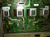
This is a closeup of the transistors
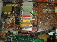
This is the top of the board with markings of my thoughts

This is the top unmodified
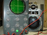
Oscilloscope with settings (settings that I turned dials to figure out). It still has the left side hooked up as well as the cheap speaker. (volume set to 0 with no input)
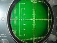
This is what the right side looks like with oscilloscope. (volume set to 0 with no input)
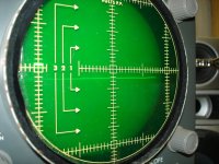
This is what the left side looks like with oscilloscope. Its a bit darker but you can still see the wide graph. (volume set to 0 with no input)

This is the under board with marked hot spots

This is a closeup of the transistors

This is the top of the board with markings of my thoughts

This is the top unmodified

Oscilloscope with settings (settings that I turned dials to figure out). It still has the left side hooked up as well as the cheap speaker. (volume set to 0 with no input)

This is what the right side looks like with oscilloscope. (volume set to 0 with no input)

This is what the left side looks like with oscilloscope. Its a bit darker but you can still see the wide graph. (volume set to 0 with no input)
ha ha ha ...this is a sorry excuse for an osciloscope ..... just Joking
your amplifiers are production models .... meaning no matter how many tricks you do on them they will always be average ....you cant expect mods that will convert those amps to something better or high end .... ( but still they will produce happilly a lot of music for years !!!! )
by the above rule your approach should be limmited to bring both amps to original state and/or some small improovement
the above approach is relativelly easy and cost effective ...any other approach will result to witchunt ( to my opinion )
so since we difine what you need to do, your task is easy but still will need skills and expirience eventhough what you need to do is simple still cannot be eassily done by an amature and or be guided by endless posts or emails ...
so here is some help and a few facts and see what you can do from there
----replace all electrolytics smallones are more importand
---- clean up properly all switches and pots
---- check , double check , triple check all solder joints especially the ones that have been under thermal stress ,remove boiled soldering, apply new ,clean
---- replace any passive parts that look that have been thermally stressed
---- replace amplifier idle trimmers with new preferably multi turn
then as about the rest ...if you can follow procedure , take one step at a time, and RTFM then you will also get some more help from this http://www.diyaudio.com/forums/solid-state/136261-vintage-amplifier-repair-upgrade-manual.html that will also provide some trouble free start up tips after the repair
presumably will talk again .... unless you think that all this is too difficult then you talk with an expert
Last edited:
Thanks for the reply, I will follow what you say.
Just to clarify...I'm not trying to mod the receiver for better sound...but repair the crackling that comes through the left speaker (sounds like someone keeps messing around with the connections like hooking and unhooking the speaker). My secondary objective is to learn so the next time (my other receiver...which looks much more complicated) will be easier.
I realize this will take time, but using what little knowledge I have, I have limited the problem to a specific area (Its labelled in the 3rd picture). I'm not sure what one of the components is (my lack of knowledge), but right now I'm thinking of swapping components with the right side to eventually see when the problem crosses over. If and when I do find the problem by this method, I will try to analyze the component every way I can think of (volt meter, om meter, diode test, cap test, etc..) to gain experience in noticing the same problem component in the future -- especially if my next repair doesn't have an identical setup like the right side in the reciever.
The component I am mentioning is labeled in the 3rd picture. It has 6 pins in total- 3 pins on each side that are labeled b c e on the board. I'm thinking it stands for base collector emitter. Ive never seen a transistor look like that and it has something rubber around it so its hard to see what it is.
- Status
- Not open for further replies.