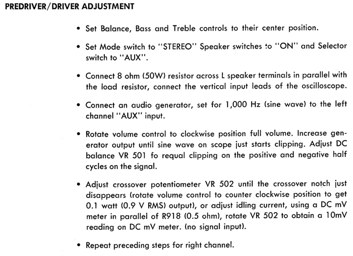
Learning as I go... Just finished recapping my Harman Kardon 330A receiver. Bought my first oscilloscope and am trying to execute the "Predriver/driver adjustment" indicated in the 330A manual.
1) On the fifth step, both channels already seem to show fairly balanced clipping. But each has a sort of double clip on one side. The right channel shows it on the top and the left on the bottom. I.e. two different clipping levels are visible at the same time on one half of the waveform. Not sure why, or which I should reference were I to adjust to perfectly balance the clipping.
2) On the sixth step, well I'm confused by the instruction. What's the crossover notch and is this something I'd see on the scope? I need help parsing the paragraph. It looks to me if I read it right that everything up to "(0.9 V RMS) output)," is one way to do it and everything after is another method, yes? Should I use the scope or a vu meter to measure the 0.9V RMS, and would that be measured across the speaker output with the dummy load in place?
Any pointers much appreciated - thanks!
-Mark M.
Your first question.
It is very important to detect the very first clipping you can see.
As theese are visible both on the positive and the negative side.
If the clipping appeares on only the one, and then gets to this "double clipping", you will need to reduce the clipping on that side first. Se the clipping appear, adjust VR501 until it disappeares, adjust volume until it reappeares again, adjust VR501, and so on. All the time detecting if clipping appeares on the opposite polarity of the curve.
Second question:
As the signal crosses the zero volt line on Your oscilloscope You will se that the signal might make a tiny jolt. This jolt is the crossover distortion.
You may have to adjust Your scopes sensitivity a bit to see it.
If you don't see any jolt, just turn the VR502 anti clockwise till it appeares, and then adjust as the instructions tell you.
The alternative method is to adjust VR502 until you meassure 10mVDC over R918.
This adjustment is to insure that the bias is set so crossover distorsion is brought to a minimum.
Thanks for your reply! Second answer I understand, excellent. First answer: I will go back and follow your direction; since the clipping looked pretty balanced on both halves of the waveform I didn't attempt adjusting anything. But maybe by adjusting VR501 I can eliminate the double clipping; will update once I get back to it - thanks again!
You need to detect the even slightest trace of clipping, thats all.
And the adjust until the same clipping appeares on both top and bottom.
If the clipping is dramatically different, you will need to sort out why the balance in Your amp is shifted. A good amp should have symmetrical clipping.
And the adjust until the same clipping appeares on both top and bottom.
If the clipping is dramatically different, you will need to sort out why the balance in Your amp is shifted. A good amp should have symmetrical clipping.
OK I did that. The clipping was already very close to even but I made it more or less perfect.
Regarding the zero crossing, I could see a VERY small blip at zero if I turned the trimpot all the way to one end. As soon as I came off of the extreme position, it disappeared. So I left it at that point where it just disappeared; it was the same for both channels.
Thanks again for your help!
Regarding the zero crossing, I could see a VERY small blip at zero if I turned the trimpot all the way to one end. As soon as I came off of the extreme position, it disappeared. So I left it at that point where it just disappeared; it was the same for both channels.
Thanks again for your help!
- Status
- Not open for further replies.