My learning curve just got too steep on this junk-pile 1977 Hitachi HA-330. I hoped to avoid a Help Post, but here I am. Help! Thanks for this site btw.
So. When I tested the amp, it made a ton of noise, the heatsink was too hot to touch and there were many volts of DC at the outputs. I pulled a few electro-caps and they were all way, way over spec. I was hopeful that a recap and idle adjustment would do the job, but it only did most of it.
I was still left with about 140 / 90 mV DC at the outputs. Voltages in the tone section (600's) were messed up and unbalanced so I pulled Qs in there and elsewhere -- and with a Chinese Amazon component tester, "measured" some serious imbalance left to right in about half the transistors. I also pulled all blue "metal" resistors in the amp/preamp section (700's), and they were ALL way over spec. I replaced those and all the "metal composition" resistors with metal film.
All the original tan metal film resistors in the amp/preamp and protection circuits were perfect, so I lost interest in desoldering more elsewhere for testing.
I also replaced almost all transistors as their hFe's looked mismatched according to Comrade Component Tester (e.g. Q601's pair of 2SC1344 were 176 hFe at 1.6mA vs 645 hFe at 6.2mA -- a lot of gains and currents were messed up). There are three pairs of Q's in the preamp and only one set was ok -- but I did them all in classic noob fashion because it's easier to buy parts than to really figure out how all this works.
So what did this get me? Nicely balanced 125mV at the speaker terminals -- that's what. Out of frustration (well, fun, really), I swapped the drivers to see what would happen. Nothing other than a higher idle current. Now I'm lost. I hope it's the output transistors, but I suspect it's something that I don't fully understand like an imbalance that's getting amplified in the signal path. I measure slightly out of spec voltages across the amp (say .83V vs .75V or 1.4 instead of 1.1). The fact that it's balanced has me worried.
In the preamp: BC566 (with CB legs swapped) for 2SA836
KSC1845Y for 2SC1344
The voltage at the output Q's is close to spec except for 125mV DC where it should be zero.
In Tone:
KSC1845Y for 2SC1344. Very even left to right.
I didn't swap or test the two T0220 transistors in the power supply after rectification. Power supply voltages check out.
The swapped Protection Q's are probably irrelevant. It works like it should now. There was no relay delay before -- or a really short one.
It sound tests fine a low volume but the DC has an effect beyond that. It is dead silent also -- so that's good.
If you can tell me where to measure -- or even what to learn -- I would be very grateful.
Last edited:
For the benefit of future HA-330 searchers, I'll update this.
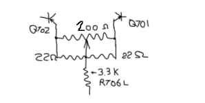
It dawned on me that my problem was probably going to be mis-matched transistor push/pull pairs. Since NPN Q701 feeds PNP Q702 and Q703, I figured that they should be more complementary... Since Q701 are KSC1845, I swapped the BC556 for KSA992 after finding "matches" with the component tester. I got down to an even 97 and 95mV.... Then I replaced the KSC1845's with a pair of the highest gain I have... Now I'm down to 82 and 83mV left and right. I wish I had higher gain KSC1845's to continue the experiment... and I wish I had a curve tracer.
I do have lower gain 992's, so maybe I'll swap one channel and see what happens...
Ah! Thanks! Isn't that cheating? I'll do that for sure. I have some blue Bourns 1K'ers... Five Digikey orders for one amp is enough!
the trim pot should be no bigger than 200r,
the 22r can use 30r or 39r, (the smaller the more precis. the bigger the more range.)
the 22r can use 30r or 39r, (the smaller the more precis. the bigger the more range.)
FYI
You can go to search here in Diyaudio
Anistardi Pelatuk Amplifier
in the pictures of #44 ,
you can find more design of this kind for your ref.
You can go to search here in Diyaudio
Anistardi Pelatuk Amplifier
in the pictures of #44 ,
you can find more design of this kind for your ref.
Last edited:
Thanks you thank you. Advice taken.
Interstingly... I swapped to lower gain 992s and it got worse, so I used the highest I have (460 range vs 420) and got DC down to 60mV. That's good enough but I'll get trimmers with the next Digikey order -- for the fun and experience of it. I'll get a scope too.
Interstingly... I swapped to lower gain 992s and it got worse, so I used the highest I have (460 range vs 420) and got DC down to 60mV. That's good enough but I'll get trimmers with the next Digikey order -- for the fun and experience of it. I'll get a scope too.
I suspect that much of what you are seeking to achieve is far tighter tolerances than the amplifier was ever intended to deliver.
The output offset of a typical power amplifier (certainly the vast majority from the 70's!) for example is predominantly defined by the input stage bias current and resistance to earth (or the output).
Without an active DC servo this will in general never be zero. This also does not matter that much...
The HFE of general transistors varies over abuse range. Both as a function of current through them as well as voltage... etc. Any reasonable design considers this and within reason HFE is not a concern.
That said a HFE miles below spec (I would normally start worrying at a HFE of 100 or so) then start checking.
Remember most multimeter are ok to say the transistor works, but the measurement is at a very low current and cannot be considered as more than indicative of the transistor health.
I just pulled up the circuit diagram. The input differential pair has 22k to the output and 100k to ground on the input side. You will always have an output offset voltage - not that it matters.
in the schematic
it marked 0v at the output.
the 22k control the feedback ratio with a 470r and a 100u/6.3v capacitor.
the 100k is needed in the differential stage.
we can always adjust the output voltages at 0v or near 0v with or without trim pots.
it marked 0v at the output.
the 22k control the feedback ratio with a 470r and a 100u/6.3v capacitor.
the 100k is needed in the differential stage.
we can always adjust the output voltages at 0v or near 0v with or without trim pots.
I think that you are overlooking a perhaps subtle point i was making.
The input differential pair have a base bias current, which is dependant on their hfe, collector current and balance of this.
All things being equal the output voltage will have an offset from zero volts to generate the required current through the 22k feedback resistor. There will also be a voltage across that 100k resistor on the input side of the differential pair.
So for notionally matched differential pair transistors and currents this circuit starts off with an offset as a consequence of the different resistances. On top of the necessary offset required to support the bias current.
Options to achieve real zero output voltage are active, or will really imbalance the diff pair.
As stated though, this is really irrelevant on terms of performance.
- Home
- Amplifiers
- Solid State
- Hitachi HA-330 from a free-pile (Help!)