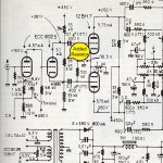
I found this circuit in an old French "L'Audiophile" book describing a PP amp designed by Jean Hiraga. The circuit looks conventional, except for the phase splitter which (the author claims) is an "improved" version of the classic Concertina (aka split load or cathodyne) circuit. The "improvement" consists in the addition of a single resistor connected between plate and cathode of the splitter tube, which looks like positive feedback to me. I've never seen this circuit used anywhere and am wondering what are the real advantages (if any) of this circuit in comparison with the classic Concertina phase splitter. I breadboarded this circuit and confirmed it is stable and works quite well, though I didn't measured all the electrical spec's yet.
Any thoughts ?
Any thoughts ?
Attachments
Since it's directly in parallel with the triode it effectively becomes a portion of ra, so I suppose you could argue that it has a linearising effect on ra. But it also reduces the effective gm at the same time, so I would question its usefulness. Maybe its meant to improve recovery time from blocking distortion?
Here's what the author says regarding the improvements (translated from original french text):
... we can use three resistors of the same value, in this case it looks like the input voltage is increased by 33% and the loads multiplied by 66% from their initial value. Consequently, this will increase the gain (which is between 0,7 to 0,9 for a classic Concertina) to a value close to 2 (when µ raise), as well as an increased bandwidth...
I understand the increase in gain (a side effect of any P.F) but the positive effects on the frequency bandwidth is less clear to me.
Maybe its meant to improve recovery time from blocking distortion?
If you get blocking between the cathodyne and the following voltage amp, the design is severely flawed. The circuit already has 100% feedback, so this won't really linearize it-in fact, since it effectively makes the loadine more vertical, I would expect distortion to be higher. (Remember, the outputs at plate and cathode are equal and opposite, so the center of that resistor is at ground) I am doubtful that the gain increases to 2.
I wonder if this is one more case of trying to fix a non-existent problem...
Think what a gain of 2 will mean. You raise the grid by 10V, and the cathode goes up 20V. The grid-cathode voltage has shifted by 10V. Do you really want your phase splitter staggering between cutoff and grid current? This is a daft idea. Why am I not surprised?
And when did positive feedback increase bandwidth and reduce distortion?
And when did positive feedback increase bandwidth and reduce distortion?
Maybe he means that the gain from cathode to plate is 2? Either way, this is not positive feedback, it's just an extra load to drive.
Think what a gain of 2 will mean. You raise the grid by 10V, and the cathode goes up 20V. The grid-cathode voltage has shifted by 10V. Do you really want your phase splitter staggering between cutoff and grid current?
Seems logical to me too.
And when did positive feedback increase bandwidth and reduce distortion?
Never. PF usually has a detrimental effect both on distorsion and bandwidth.
it's just an extra load to drive.
That looks like it. Since it's connected to the two opposing phases before the caps and input resistors to ground, will this have any effect in canceling distortion, like some crisscross circuits a la early Audio Research? Or it reminds me of an input transformer with no center tap secondary and shunting it a resistor and then a pair to ground which I saw that in some circuits. I have no idea, just speculating. It is interesting though.
It's not even that. It's an extra load, no more, no less.
Pretend the 39k resistor is two 19k5 in series. At their junction, the voltage is zero. So the effect is the same as paralleling the plate and cathode loads with 19k5 each.
Pretend the 39k resistor is two 19k5 in series. At their junction, the voltage is zero. So the effect is the same as paralleling the plate and cathode loads with 19k5 each.
Maybe he means that the gain from cathode to plate is 2? Either way, this is not positive feedback, it's just an extra load to drive.
Nevertheless, JH wrote (p.14):
... (la résistance) introduisant de la sorte une réaction positive de tension,...
which means:
... (the resistor) introducing in this way a positive voltage reaction...
Because of the DC coupling with the previus stage, this resistor just reduces the idle current in the PI by some 3 mA and, yes, at the expense of an extra load.
Gain is more probably halved than doubled.
Comprend pas / Can't understand . . .
Yves.
Gain is more probably halved than doubled.
Comprend pas / Can't understand . . .
Yves.
It is an extra load independent on grid currents of output tubes. It decreases linearity of the stage that is somehow compensated by global negative feedback, no big deal, but when the amp is overdriven it sounds les nasty as the result.
I.e. it is the way to make the amp little worse in normal conditions, and less worse when overdriven.
All author's explanations sound like marketing speech to me, total nonsense mixed together from technical words.
I.e. it is the way to make the amp little worse in normal conditions, and less worse when overdriven.
All author's explanations sound like marketing speech to me, total nonsense mixed together from technical words.
Nevertheless, JH wrote (p.14):
... (la résistance) introduisant de la sorte une réaction positive de tension,...
which means:
... (the resistor) introducing in this way a positive voltage reaction...
He was wrong.
He was wrong.
Not completely. Feedback becomes positive when upper load hit grid current of output tube, i.e. resistance of anode load becomes less than resistance of cathode load. In all other conditions it is just a shunt.
Yes, when all is balanced (the ideal case) it will increase the load while simultaneously reducing the quiescent current in the valve. Guaranteed recipe for increased distortion?
To get useful positive feedback from anode to cathode you need a transformer. I won't say any more because I don't want to resurrect an old debate!
Surely he can't mean that, because he compares it with the normal case of 0.7-0.9 which is clearly from grid to cathode. I suspect he has misapplied the feedback equation, or something similar. It is easy to get a daft answer by blindly plugging things into a formula.SY said:Maybe he means that the gain from cathode to plate is 2?
To get useful positive feedback from anode to cathode you need a transformer. I won't say any more because I don't want to resurrect an old debate!
The phase splitter couples to a driver tube, not the output stage.
So, in this particular case it was a cliche. I.e. result of generalizing of something that was useful in certain context. It happens very often, in electronics design it is called Rule of Dumbs. Like, shunting of electrolytic cap by a film one with 10% of capacitance, like Zobel networks in output of transistor amps, and so on, including whole topologies that are suboptimal in many cases except certain ones.
- Status
- Not open for further replies.
- Home
- Amplifiers
- Tubes / Valves
- Hiraga's Improved Concertina Phase Splitter