
Member
Joined 2009
Paid Member
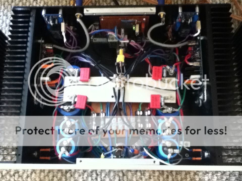
Now the amp starts to take form.
Hi Frank,
Very nice indeed, which transistors did you use?
I am buiding one of these at the moment.
Jacques
i have enough of those, but it lookse great, very nice job.....huge coolingribs.
But i was thinking--->desktop-->everything watercooled, but i havent seen it yet with audiogear.And why not?...safety ain't the isue.
Offcourse thislooks much , but i'm gonna try it. I'm not using the graphiccard at all, so i'll take that rig and i need a subwoofer amp, and a lm3886t or two (i only have 2") ), with a circuit that excists.....
), with a circuit that excists.....
Bit this build is very nice to look at....really a cool sight.
Greets richard
But i was thinking--->desktop-->everything watercooled, but i havent seen it yet with audiogear.And why not?...safety ain't the isue.
Offcourse thislooks much , but i'm gonna try it. I'm not using the graphiccard at all, so i'll take that rig and i need a subwoofer amp, and a lm3886t or two (i only have 2
), with a circuit that excists.....Bit this build is very nice to look at....really a cool sight.
Greets richard
Im using Toshiba 2SC5200 / 2SA1943.
Hi Frank,
I am interested in the biasing of the circuit and I have a few questions.
Could you please let me know the value of the bias resistor (should be ~33K according to the original Hiraga schematics) and the voltage across one of the 0.33R, without signal? At what DC voltage do you run the amp? Thanks.
Jacques
Hi Jacques, I think the bias is 47K, I will find out for you. The voltage over 0.33R and DC must wait until testing.
Hi Frank,
I used 47K in my first build but did not work properly: lots of distortion and could not reach the nominal classA bias. The outputs would stay 'cold'. It worked very well with 33K as recommended privately by Suztek (also a forum member) who built the Hiraga as well.
Cheers,
Jacques
I think he meant Single Ended but it is not. It is push-pull class A. I have built this amp and it sounds great. The bias resistor needs to be adjusted accordingly with the transistors installed. The design is dependent a lot on the transistors characteristics...
Fab
Fab
Last edited:
Hi fab
I know there have been some models of 30W.
Think I have the last one that Jims Audio sell.
I use Thosiba 1943 and 5200. You have any ide what the bias resistor sould be?
One friend have tested the print and the bias is around 1.5A.
Frank
Good look
What about "noises" on 50 Hz and 100 Hz?
Hi fab
I know there have been some models of 30W.
Think I have the last one that Jims Audio sell.
I use Thosiba 1943 and 5200. You have any ide what the bias resistor sould be?
One friend have tested the print and the bias is around 1.5A.
Frank
Hi Sagen
I have only the pcb from Jim's Audio and I have used my own parts with Njw3281/1302 for outputs. I had to rebias all stages.
In your case, it seems that your parts gives you the good output stage bias.
As long as 1.5A is not too much for your heatsink temperature (<=55C) then you are ok.
I also notice that you have long leads for your output trannies possibly to maximize their position into the heatsink?
I suggest that you use the pcb holes anyway since the heat will propagate anyway onto the whole heatsink with a higher hot spot close to the 2 output transistors but with heatsink at less than 55C the internal temperature of transistors should be ok.
Keep us posted on your appreciation of the sound!
Fab
Last edited:
Hi Fab
You mean to use one leg of the pcb to fasten the transistor so shorter cables?
Frank
That could be an option but I would rather not use wires at all but it would probably mean to relocate the boards....
On the other hand it is a very low feedback amp and less prone to oscillation than most amps...so you could probably live with wires....however I would definitely reduce the wires length to smoke it as short as possible.
Fab
Hi, now the amp is runing.
Mode from last time is solded transistors to the print.
New trafo: 600va 2+18V ( goes cooler, 45 c`on heatsink ). The bias now is around 1.5A.
It sounds great!
But have a question, got some bromine in speakers.
Goes away when signalcable is not conected, try shelded cable?
And what have you done with the chassie ground? not conected, conected or conected via an resistor?
Frank
Hi, now the amp is runing.
Mode from last time is solded transistors to the print.
New trafo: 600va 2+18V ( goes cooler, 45 c`on heatsink ). The bias now is around 1.5A.
It sounds great!
But have a question, got some bromine in speakers.
Goes away when signalcable is not conected, try shelded cable?
And what have you done with the chassie ground? not conected, conected or conected via an resistor?
Frank
Hi Sagen
I do not know what "bromine" means but is it "hum"?
Good signal cables is always a must ....
I have installed a resistor in parallel with anti-parallel diodes between PSU star ground and chassis gnd AC power. R = 330 ohms and diodes of 5A. You can also lower the resistor value down to 20 ohms or so. You can also add a cap in parallel of about 100nf or so.
See internal picture of my Hiraga amp:
http://s1298.photobucket.com/user/Fabient1/media/photo_zpsb30d35fc.jpg.html]
An externally hosted image should be here but it was not working when we last tested it.
And now enjoy the sound!
Fab
Last edited:
- Status
- This old topic is closed. If you want to reopen this topic, contact a moderator using the "Report Post" button.
- Home
- Amplifiers
- Solid State
- Hiraga 30W.