The last couple of days I was reading a book about power amp designs and one of the designs mentioned was the hill DX700.
It had to do with sliding bias and a special kind of drive to the output using a transformer.
The driver driving the transformer was just a chip amp (TDA2030).
Looking at the distortion specifications it doesn't look really bad.
Has anyone used these? and comment on the sound?
I do like to check out some of these more obscure designs.
What would a modern version look like?
A few things for modernizing could be a more modern chip amp (lm3886?), using a class H output but still using the sliding bias arrangement if possible.
Use a Sziklai output stage instead of just driving the outputs directly.
Less loading of the chip amplifier so less distortion I think.
I'm just thinking out loud now but the design looks like it worked good so why isn't it used anymore? I am still in the process of figuring out how exactly the sliding bias works
Buffer with a low output impedance across a wide range, transformer for voltage gain, and then complementary output.... sounds like Nelson's famous M2X to me, sans the sliding bias.
There is not that much information about these cabs. I can find that they where used at the live aid concert in the eighties.
Looks like horn loaded cabs. little bit of a weird design.
For the amps, I've read the other tread but can't find a lot of schematics and info.
Looking at the specs and considering they where build in 1978. The days when output transistors had low gain and where low speed it looks fine on paper.
I just wonder if anyone has experience with them?
I've read that the transformer is a 1:1:1 design so no real voltage gain except the 2 secondary windings for 1 primary(= X2)
So I am a bit puzzled as where the voltage gain comes from. The TDA2030 is power from +/-15v so maximum swing will be a little less then 30vpp
The output stage however has 70v power rails. Usin a 1:1:1 transformer the maximum swing will be less then 60vpp so....

Vt1 and 2 pre-amplify the signal (like your 2030). Vt3 and 4 receive the base current from the transformer and amplify the signal to the rail (70V).
Last edited:
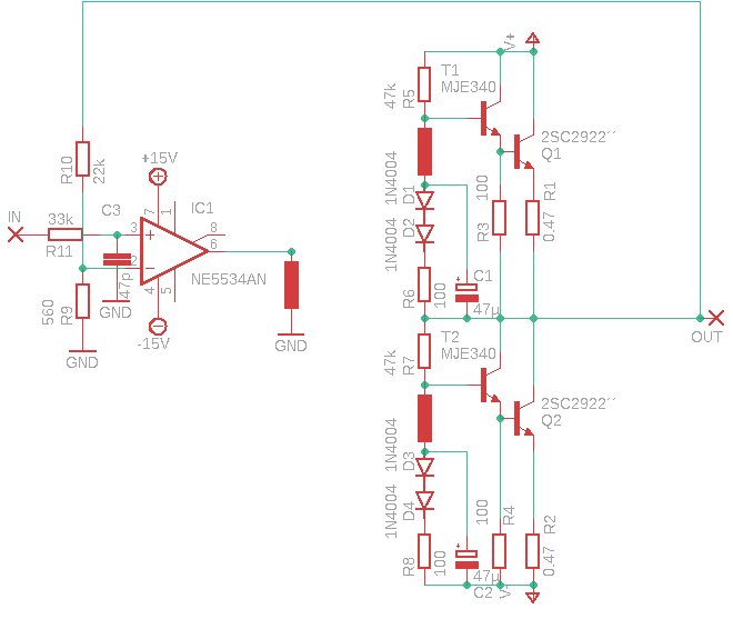
Ok so I tried something in ltspice.
Based on the basic drawing of the hill dx700
I added drivers to the output so the current in the transformer is lowered and for lower power (testing) a normal opamp can be used to drive the transformer.
Then I added diodes to thermally compensate the outputs. Don't know if this is a good way to do it but for a stable bias this is mandatory to have thermal compensation.
Bias was set around 1A idle but slides down when driven hard.
The resistor values also had to be made higher (lower current because of using drivers/darlington configuration)
It only exists in simulation yet. Needs some tweaking and compensation I think.
One pair of transistors could have maximum voltage of around +/-40v I think.
More voltage and power = more output pairs but a standard opamp will not be able to apply the needed current. Especially in lower loads.
Tripple darlington could probably be used then.
Distortion in ltspice looks good getting sims around 0.005% but I think this would be a lot different in real life.
If i find a suitable transformer I'm gonna breadboard this one and see what comes out.
Specification
http://www.hill-audio.com/wp-content/uploads/2016/07/Amplifiers_DX700_brochure.pdf
The transformer can be wound on a "Ш" core with four wires (200 turns).
The two windings are connected in series (start-end-start-end). This will be primary. The remaining two windings are secondary.
TDA2030 can supply 3A current. Voltage + -12v.
10 transistors per arm. 70v at 4oma 17a.
One output transistor 1.7a. Working voltage 200V.
Last edited:


Thanks for all those schematics.
Looks like a lot of russian made 🙂
Gives me a lot of information to think about.
I also checked the dissipation with 45v rails (in simulation).
When idling the average dissipation in the output is in total around 60W. I backed of the standing idling current a little bit.
Then at the onset of clipping the average dissipation in the output is only 42W
The power output was a continous 100W sinewave. (0.033% distortion)
This means 70% efficient at full output.
Interestingly The output dissipates more at idle then at full output.
Then at quarter power dissipation is around 54W with an efficiency of only 31%
So the sliding bias does seem to work and the dissipation in the output is almost constant.
distortion at a quarter output is only 0.001% according to spice (I have a hard time to believe that). It probably also depends on the opamp used but there are some great opamps to choose from.
When going full output distortion rises and this seems logical as the output now behaves more like class B.

- Home
- Amplifiers
- Solid State
- Hill Audio Sliding bias