dinu said:......................
Thanks. I guess this is a soft start. My problem is capacity. I'm turning on 2KVA and about 272,000uF per monoblock. I need a very high current, high power unit. Those ramp up devices from Crydom are pricy but definately suit my needs. What are these good for?
look this......pdf file,460kB........simple and effective
it will be for week or two at :
http:\\czsr_bac.on.neobee.net\soft.pdf
I like it. Is it available as a kit o do I need to build from scratch? I just want something to bolt in. That's why I thought this part would have been perfct.
http://www.crydom.com//userResources/productFamilies/96/crydom_MCS.pdf
Buy it, wire it, forget it. Please check it out and give me your opinions.
I'll also check peranders site.
http://www.crydom.com//userResources/productFamilies/96/crydom_MCS.pdf
Buy it, wire it, forget it. Please check it out and give me your opinions.
I'll also check peranders site.
dinu said:I like it. Is it available as a kit o do I need to build from scratch? I just want something to bolt in. That's why I thought this part would have been perfct.
http://www.crydom.com//userResources/productFamilies/96/crydom_MCS.pdf
Buy it, wire it, forget it. Please check it out and give me your opinions.
I'll also check peranders site.
from some reason I can't open or download this link
dinu said:Works for me. How about if you go to digikey.com and lookup digikey part # CC1583-ND
An externally hosted image should be here but it was not working when we last tested it.
fine with me
")
That's the one. The only problem is you have to supply (depending on the model options you pick) 5 and 8-32V. One more PSU. It works by varying the turn on time to coincide with decreasing phase angle (potential) during the ramp up period. After that initial ramp up, the unit is on but still drops about 1.5V therefore dissipating some power. I guess is uses high power SCR diodes. There's also a bit of leakage current, about 10mA.
New Pictures
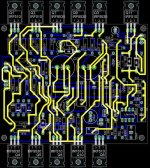
Well, the boards are almost done> Here's a pic of the completed front ends and some output boards. The assembly with the large heat sinks is Bob's PSU 2.2 board. I haven't tested yet. The TO220 devices on the front ends will be installed as soon as I have the chassis done> Right now, it exists in ACAD only. It looks very promising though.
http://i125.photobucket.com/albums/p70/dinui/IMG_1175.jpg
http://i125.photobucket.com/albums/p70/dinui/IMG_1179.jpg
I found a 12v 1..5A supply premade from MPJA for 6 bucks. A voltage divider from that will give me the 5V or so I need for the ramp time voltage.
Bravo on the board, by the way. Very nicely done. It went together very easily and looks great.
The only thing I'm a bit bummed about is a dumb mistake I made on the output boards. The header pitch is 2.54, way too small. Wish I'd gone bigger. I'll have to wire right to the board and use free hanging connectors.
Progress is slow but steady. While I'm waiting for matched fets to arrive, I've been keeping busy with some of the hardware items that I can do myself. The fets on the front end boards will be attached to two copper plates weighing about 2 lbs each. I know it's overkill but at this point, that's almost exactly the goal. Here's a pic.
http://i125.photobucket.com/albums/p70/dinui/IMG_1203.jpg
http://i125.photobucket.com/albums/p70/dinui/IMG_1203.jpg
Wow, Glaciers move faster than I do.
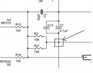
Amazing how moving and getting married will slow things down. Well, now I have a proper shop and have picked this up again for the last piece of the puzzle. The front end works great after a couple of tweaks. For anyone using these boards please note that P3 and P2 are reversed. You have to start them in the full clockwise position. Lastly, there is an eronious connection in the board itself. If you look at my schematic, I mistakenly connected the junction of R3 and R27 to the -Drv pin. Problem!
I had to cut a little hole in the board between R23 and R24 to disconnect this trace and then repositioned R26 on the board and it all works.
Another thing to note is that, unlike the original boards, Z3 and Z4 do not have a separate connection to ground and you'll see a crossover notch at the output when setting up the front end if R81 is installed. I suggest putting off installation of either R81 or the zeners until you're ready to plug into the output stage. I set up the front end with the zeners installed and no R81. You can pick up the output from the R23/24 junction.
So all that aside, I bought a really nice chassis from Hifi 2000. I got tired of metal working and this is much nicer than anything I could have made even though I have an actual work bench now.
Finally, I need to get an output power transformer into this monster. I planned on 65v rails so the transformer of choice would have been a 45v. I found a gorgeous 2.4Kva unit unfortunately, the closest I can get to my planned 45V is about 54. That would give me 76v rails. Do any of you know a good way to drop about 10v? Maybe a high current regulator. Maybe I don't need to drop the voltage. Maybe the best choice would be to just drop the quiescent current a bit and call it a day.
Any suggestions?
Mega,
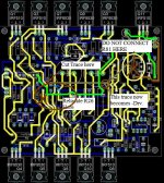
That's it. You have to cut a hole in the board as shown in the attached pic to disconnect the junction of R3R27 from -Drv. R26 is now in the wrong position so I just soldered it to the leads of R24 and R12 as shown.
VERY IMPORTANT. You can not install R81 in it's marked board position because now you are essentially connecting it from -drv to output. I plan to install R81 as a 3 position switch that has leads going to the board attached to resistor leads.
That's it. You have to cut a hole in the board as shown in the attached pic to disconnect the junction of R3R27 from -Drv. R26 is now in the wrong position so I just soldered it to the leads of R24 and R12 as shown.
VERY IMPORTANT. You can not install R81 in it's marked board position because now you are essentially connecting it from -drv to output. I plan to install R81 as a 3 position switch that has leads going to the board attached to resistor leads.Attachments
http://i125.photobucket.com/albums/p70/dinui/HRSCHEMATIC.jpg
Here's the schematic again. I have tried R81 open and closed and the results are the same. I am wondering if the servo resistors R31 and 33 are having an effect on the output impedence. Also, I made R25 and R26 20K instead of 10K just to keep dissipation down a bit because I have 80v rails on the front end. Are they considered part of the output impedence?
Here's the schematic again. I have tried R81 open and closed and the results are the same. I am wondering if the servo resistors R31 and 33 are having an effect on the output impedence. Also, I made R25 and R26 20K instead of 10K just to keep dissipation down a bit because I have 80v rails on the front end. Are they considered part of the output impedence?
- Status
- This old topic is closed. If you want to reopen this topic, contact a moderator using the "Report Post" button.
- Home
- Amplifiers
- Pass Labs
- Higher power A75.