Hello everybody,
Please pardon me, for posting in a diyAUDIO forum about a non-audio topic, but there seems to be so many knowledge floating around here, that I hope you might be able to at least tell me, if my idea has a chance to work.
We do not drive speaker coils with our application, but charge ions in liquids by capacitive coupling. So we have square signals of different voltages as signal shape. We need frequencies of up to 130kHz to change from one voltage to the next, but at very small power levels. Until now we use a classic class A/B op-amp. Trying to cramp this into a small voume box, we run into thermal problems. Active cooling is difficult due to the space constraints.
So the idea is, to use a class-D amp instead of class-A/B, to reduce the power consumption.
Problems I see:
Best regards
Please pardon me, for posting in a diyAUDIO forum about a non-audio topic, but there seems to be so many knowledge floating around here, that I hope you might be able to at least tell me, if my idea has a chance to work.
We do not drive speaker coils with our application, but charge ions in liquids by capacitive coupling. So we have square signals of different voltages as signal shape. We need frequencies of up to 130kHz to change from one voltage to the next, but at very small power levels. Until now we use a classic class A/B op-amp. Trying to cramp this into a small voume box, we run into thermal problems. Active cooling is difficult due to the space constraints.
So the idea is, to use a class-D amp instead of class-A/B, to reduce the power consumption.
Problems I see:
- I did not find any ICs on the vendors' shelves that allow output frequencies of up to 130kHz (instead of the typical 20kHz in audio); so we probably have to tackle a discrete design. Is there anything available for our purpose that I did not spot?
- Our first thoughts are to go up to 20MHz frequency to be able to shape the edges: We are however afraid that this would lead to massive losses due to the capacitance of the transistors. Can this be solved with dead time? Are their suitable transistors available with low capacitance?
- With regard to the low-pass filter we have no speaker coil to be used as inductance. Worse, we have capacitors as load. What would be your approach to handle this?
- Can the problem be simplified by accepting higher distortions and imperfect signal shape? The only thing we really need in the end is the correct amount of ion charge; it is not important at which time of the loading signal period they ended up there. What we need are steep attack/decay on the signal edges of the rising flank and exactly the same amount of charge, i.e. very good reproducibility.
Best regards
Hi,
I think you should give all the paramaters you know:
Like input- output-voltages (and thus needed gain),
better description of the load impedance/current need.
Option 4 could be easily realized with a fast opamp followed by a (simple) discrete Class-B output stage.
I think you should give all the paramaters you know:
Like input- output-voltages (and thus needed gain),
better description of the load impedance/current need.
Option 4 could be easily realized with a fast opamp followed by a (simple) discrete Class-B output stage.
[*]I did not find any ICs on the vendors' shelves that allow output frequencies of up to 130kHz (instead of the typical 20kHz in audio); so we probably have to tackle a discrete design. Is there anything available for our purpose that I did not spot?
See this)))
Attachments
Sorry, what do you mean by GaN?See GaN
Unfortunately limited to 100kHz, but 130kHz needed. Also 1W in idle already, so most probably not the power efficient device we look for.TPA3251
Like input- output-voltages (and thus needed gain), better description of the load impedance/current need.
Option 4 could be easily realized with a fast opamp followed by a (simple) discrete Class-B output stage.
The output voltage range is from about 20V to 300V. I have to check capacitance (no impedance) and current tomorrow at work.
Do you think:
- the dissipated heat of a class-B would be significantly better over a class A/B opamp (so no class-D needed)?
- your suggested design would provide repeatable behaviour? Deviating charge on the ions from one cycle to other cycles with the same target voltage has to be avoided.
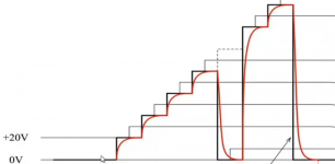
The voltage levels are discrete. The input is generated by a DAC, whose signal needs to be amplified. It looks like this:Are the voltage steps discrete? Whats your modulation source?
The red line is the old design that needs to be improved. Rise times are about 1.5µs, which was improved now with the class-A/B opamp to less than 0.5µs. The steps typically go up, bot not always with identical deltas. It can also go down to a different level than zero Volt after the top value was reached.
upto 300V @130kHz is a challenge. And 1W idle loss under these conditions - very challenging.
In case your excitation signal was sinuoidal, a resonant converter would be my preferred choice. But a 300V sharp square wave? I do not have any idea.
In case your excitation signal was sinuoidal, a resonant converter would be my preferred choice. But a 300V sharp square wave? I do not have any idea.
Ti has a few classD amp chips which switch at 2.1MHz, for example : https://www.ti.com/lit/ds/symlink/tpa6304-q1.pdf?ts=1601431633137&ref_url=https%253A%252F%252Fwww.ti.com%252Fproduct%252FTPA6304-Q1%253FkeyMatch%253DTPA6304%2526tisearch%253DSearch-EN-everything%2526usecase%253DGPN
They don't go very high in supply voltage but as your power requirements are low perhaps a transformer could be used to step-up the output voltage? It would need to be custom-wound, bifilar to get the bandwidth you require.
Btw GaN refers to gallium nitride, a relatively new technology to build faster, lower loss MOSFETs.
Sorry, for screwing up the graphics, it looked good in the preview. 🙂The voltage levels are discrete. The input is generated by a DAC, whose signal needs to be amplified. It looks like this:
I hope it is now attached correctly.
The red line is the old design that needs to be improved. Rise times are about 1.5µs, which was improved now with the class-A/B opamp to less than 0.5µs. The steps typically go up, bot not always with identical deltas. It can also go down to a different level than zero Volt after the top value was reached.
Attachments
This may be more up your ally. A proven design, and I am sure Winfield will be happy to help:
Winfield's 100W DC-10MHz 1000V/us amplifier
Practical info here:
Winfield Hill's 100W, 10MHz, 1000V/uS AMP-70 | Linear Audio NL
Jan
Winfield's 100W DC-10MHz 1000V/us amplifier
Practical info here:
Winfield Hill's 100W, 10MHz, 1000V/uS AMP-70 | Linear Audio NL
Jan
This may be more up your ally. A proven design, and I am sure Winfield will be happy to help:
Winfield's 100W DC-10MHz 1000V/us amplifier
The specs loook really good. Maybe we can reduce the footprint by lowering the requirements, the PCB shown there is just too big.
It's interesting that he offers consultancy, maybe I try to contact him by mail.
You can reduce the number of output devices if your current requirement is lower. What is the max current you want to draw?
Jan
Jan
Unfortunately limited to 100kHz, but 130kHz needed. Also 1W in idle already, so most probably not the power efficient device we look for.
...
The output voltage range is from about 20V to 300V. I have to check capacitance (no impedance) and current tomorrow at work.
...
Ah, I am sympathetic with your cause, given I do similar things professionally!
I do wonder, depending on your distortion needs, whether a class C output topology might not work? Do make sure you do really *really* need the extra harmonics of a square wave versus a sinusoid. I also wonder if the folks at Trek amplifiers have a module/etc that might work with your application? I have used in the past a couple of their high voltage amps (albeit too big for your application) that could hit your slew rate requirements. Idle losses for a 300V switcher will be killer, even if your power requirements come primarily from switching the Stern/double layer rather than bulk ion flow, i.e. low conductivity solutions.
Our current PSU is limited to 15mA, so with the 300V peak about 4.5W power. The peak current on the rising edge is 300mA.You can reduce the number of output devices if your current requirement is lower. What is the max current you want to draw?
The capacitive load is in the range of some nF only.
If the signal rise is sinusoid we would need higher voltages to transfer the same energy in the given time. Was never tested so far to the best of my knowledge. But worth a thought.Ah, I am sympathetic with your cause, given I do similar things professionally!
I do wonder, depending on your distortion needs, whether a class C output topology might not work? Do make sure you do really *really* need the extra harmonics of a square wave versus a sinusoid.
The specs of the PZD700A look good; the thought of integrating it into a small volume box however makes me doubt that our project has a chance.I also wonder if the folks at Trek amplifiers have a module/etc that might work with your application? I have used in the past a couple of their high voltage amps (albeit too big for your application) that could hit your slew rate requirements.
That's what I am afraid, too. The current caused by the ion flow is negligible.Idle losses for a 300V switcher will be killer, even if your power requirements come primarily from switching the Stern/double layer rather than bulk ion flow, i.e. low conductivity solutions.
No, so far it's just in the brainstorming phase, no Class-D breadboard experiments. How do you integrate the TC4424 to go up to 300V output?have you tried mosFET drivers? square wave to Mhz 1A output 20v BTL 40v p-p
TC4424 may work
GaN: There seem to be no p-channel variants of them. Does this rule out Class-D, or can you solve this with two n-channel ones, too?
If the signal rise is sinusoid we would need higher voltages to transfer the same energy in the given time. Was never tested so far to the best of my knowledge. But worth a thought.
To continue this bug in your brain, I haven't found off-target electrochemical/electrokinetic effects from having a modest (1% or so?) level of distortion. But my specific application is down in the audio range rather than >100 kHz, which also means I have a lot more electrochemistry going on. In your app, an ugly-looking pulse that gets it the energy dump done might work just as well as a minimally-ringing square wave, and open up a lot more energy-efficient high slew-rate designs. Obviously, I don't want to presume, but my gut is to say it's worth checking!
Genuinely interested in hearing how things go, if you're able to share.
GaN: There seem to be no p-channel variants of them. Does this rule out Class-D, or can you solve this with two n-channel ones, too?
It's absolutally normal to use only N channel MOSFET's in switching designs like Class D amplifiers.
It must be decades ago since I saw someone that knows the art that used complementary MOSFET's for low side and high side switch.
Bob Cordell is talking about such things in the chapter about Class D amplifiers in his books, that is a shame.
All the best
Stein
- Home
- Amplifiers
- Class D
- Higher frequency application, no coils