Ummm, OK really stupid question.
When I look at the plate curves for the 40 - which look awful, by the way, LOL - why do they look like it's a pentode when it's a triode?
http://www.mif.pg.gda.pl/homepages/frank/sheets/021/4/40.pdf
Very Best, Synchro27
If you read the top of the graph those are the curves of the type 41 tetrode 😛
You can assume the the curves to be just like that of any DHT, very linear, so id recommend you just use a generic set of triode curves and adjust the ip and vp scales for a chosen grid voltage step.
As far as its application in audio it really isn´t the best choice to drive those big transmitting triodes, it has too high a plate resistance and even in CF configuration it won´t be capable of providing enough current to the output tube when nearing cutoff. Besides it has a max vp of 180v so it will have a hard time driving the grid of those transmitting triodes which require around 100Vpp.
I think you don´t have any choice but to use 2 gain stages if you want to use DHT´s. If you accept this compromise you have an immense amount of tube combinations to use. For example 40 driving a 2a3/300b/45/10 which then drives the power tube will give you all the headroom you need.
LOL, now that you mention it, those curves make a lot more sense as a tetrode. Reality and sanity has been restored.
I'm sure you're right...a 40 with a quiescent current of 0.2 mg is not a good candidate as a driver, even in CF mode.
the 1H4G with a quiescent current of 3 mA seems a stronger candidate.
How would I calculate how much current a CF should be running to drive the 35T?
The easy answer is to just use two mosfets, as in tubelab.com's Power Driver circuit, but I am reluctant to bring in solid state, I'd rather keep it all tubes, and direct heated filaments at that.
Very Best, Synchro27
Hmmm, I have two schematics to upload...both in .jpg....but I dunno how to do it.
When I click on the insert image button, it asks me for a url. Would someone please explain how I associate each of my .jpg with a url so it can be uploaded?
Very Best, Synchro27
When I click on the insert image button, it asks me for a url. Would someone please explain how I associate each of my .jpg with a url so it can be uploaded?
Very Best, Synchro27
first schematics
Thanks, Kevin, much obliged.
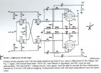
This amp is based on Alan Kimmel's Mu Stage paper.
I have uploaded two attachments (well, I THINK I did...):
the page from Alan Kimmel's article showing his method for a differential I/O Mu Stage,
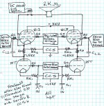
and my schematic for my version as the output stage for my amp/speaker combo.
Since the speaker is a special DIY high impedance speaker, and it's running at 1.5 KV above ground, LOL, the output stage will be incorporated INTO the speaker.
All comments are welcome, including those that tell me this is a terrible idea LOL. However, if you're going to criticize, please explain in detail so I can either fix the problem, reject the criticism, or explain why I have incorporated an odd feature 😀
Very Best, Synchro27
Thanks, Kevin, much obliged.
This amp is based on Alan Kimmel's Mu Stage paper.
I have uploaded two attachments (well, I THINK I did...):
the page from Alan Kimmel's article showing his method for a differential I/O Mu Stage,
and my schematic for my version as the output stage for my amp/speaker combo.
Since the speaker is a special DIY high impedance speaker, and it's running at 1.5 KV above ground, LOL, the output stage will be incorporated INTO the speaker.
All comments are welcome, including those that tell me this is a terrible idea LOL. However, if you're going to criticize, please explain in detail so I can either fix the problem, reject the criticism, or explain why I have incorporated an odd feature 😀
Very Best, Synchro27
Attachments
Glad I could help, and it does look like a very interesting project.
For safety make sure that any exposed metal on the speaker system is grounded, and that the driver VC is not accessible to human contact.
One other concern is the voltage differential between the pole piece, magnetic circuit and the VC, insulating against these sorts of voltages in a moving structure could prove challenging.
Finally 2K for a VC is about 2.25X higher than anything I have heard of, I suspect bandwidth could be a problem if you need more than a kHz or two.
Thanks, Kevin.
As usual, I forgot people can't read my mind. It's not one discrete speaker, it's an array of 250 small full-range speakers all in series - and the deep bass will be split off before the entire amp to drive a mosfet plate amp for a separate woofer/sub.
So, the voltage across any one speaker is small.
But one can certainly see that running speaker wires around a room, carrying a DC potential of 1.5 KV, is not going to be ultimately healthy for the cat.
I did this before, years ago, and it worked wonderfully - until the output capacitor (not in this version LOL) blew up because I had completely forgotten that I needed like...uh...THREE of them in series to handle the total voltage ROTFL.
When the cap blew, a big electrolytic, it shot a column of steam to the ceiling, just missing my left elbow - which is the reason I still have a left elbow - and all 250 of my speakers promptly fried themselves into molten copper, since what was left of the electrolytic was a bed of glowing slag that continued to conduct very nicely in DC mode.
That version used 6550's for the pentodes, above some triode I've forgotten, with a B+ of 700 V.
This version is considerably meaner, with a B+ of 3 KV and 813's for the pentodes.
But I want headroom - the problem with a mu stage is it clips hard or even blocks when overdriven, so you need TONS of headroom. This is designed to be able to get up to 300 watts output without clipping (I haven't looked yet at whether I'll need paralleled 813's to handle the current); with 250 speaker cones, the speaker array is, en toto, so stiff - and efficient - the surface area total is vast - that I think it's only going to need 25 watts nominal level to fill a room; the rest is headroom for transients. But...we'll see 🙂
At a later date, as this schematic develops, I do wish to add a soft-clipping circuit to the mu stage; I think that's going to be essential to get good sound, since there is almost no such thing as an amp that never clips. I think this will entail both adding a soft clip circuit to the CCS's (or if the CCS's are tube based, maybe that won't be needed) and a soft clip circuit to the Mu Stage pentodes.
Another consideration re: clipping, is to so dimension the output stage as to ensure that the triode clips first, so that the pentode never clips. Of course, that should be a design element of dimensioning any Mu Stage, and I think that would be a useful addition to Kimmel's article. One way of doing that would be to give the triode plate ( 1/2 B+ - clipping room) rather than 1/2 B+ precisely.
Very Best, Synchro27
thinking about how to servo the output of the pentodes, it occurs to me it might be easier to do so by controlling the screen voltages of the two 813's, rather than controlling the bias of the control grids.
Does anyone have an opinion on servo'ing the screens - instead of servo'ing the control grids bias's - as the method of keeping DC balance across the outputs?
Very Best, Synchro27.
Does anyone have an opinion on servo'ing the screens - instead of servo'ing the control grids bias's - as the method of keeping DC balance across the outputs?
Very Best, Synchro27.
I was just thinking that such amplifier could feed stators of an ESL without any transformer between amplifier and stators.
At a later date, as this schematic develops, I do wish to add a soft-clipping circuit to the mu stage; I think that's going to be essential to get good sound, since there is almost no such thing as an amp that never clips.
If you are using a digital source, it's trivial to eliminate the possibility of clipping, by paying attention to the gain structure.
Sheldon
I was just thinking that such amplifier could feed stators of an ESL without any transformer between amplifier and stators.
Yes, precisely, I have gotten side-tracked by life, which tends to happen to most of us, I think, and have not made progress on this project for quite a while, but my original goal was indeed to direct drive ESL speakers without a transformer. It has always seemed to me to be the height of nuttiness to try to maintain fidelity through the extremely high-ratio transformer required to drive ESL's.
My other objective was to make a very high impedance speaker and drive it directly also, and this objective remains very much in view, I did it once with quite marvelous results, and then was in the process of doing it again but with a far higher impedance and a much larger voltage swing on the direct drive output when....again...life...close to death, but part of life...happened once again. It's on my bucket list, here's hoping I get around to it again.
If you are using a digital source, it's trivial to eliminate the possibility of clipping, by paying attention to the gain structure.
Sheldon
That is true. In year's past I would have objected to your premise, but I have changed my mind.
I still vastly prefer vinyl, but vinyl is a hassle, there's no way around it, and sometimes the convenience of digital sources is welcome.
My objection to digital was, of course, the loss of the special quality vinyl brings to audio, but I have since found that the euphonia added by an amp with triodes and reduction or even elimination of negative feedback is so appealing that much of the enjoyment lost by digital sourcing is replaced fairly effectively.
Which answers why recordings can be made - and were made - with so much solid state equipment and tape recording before transferring to vinyl, and the sound was so bloody good - the transfer to vinyl and playback from vinyl added in euphonics that made the sound pleasurable; in the same way a triode amp with negative feedback reduced does the same. So, bring on the digital! What the hell, I'll put the euphonia back in with my amp and my direct-driven speakers.
if you're going to criticize, please explain in detail so I can either fix the problem
No criticism, just an observation based on my experiences with DC coupled circuits, including something similar at a much lower voltage and power level. You probably need a DC servo to keep the two speaker leads at the same DC potential. Two servo systems connected into the same DC coupled circuit is asking for a tug of war between them which degenerates into a multivibrator or flip flop. Your diagram does not show where the servos sense the current or voltage, so it's hard to say how to fix it, but I usually servo control the most sensitive point (triode grids) with the least gain possible to cover the needed range, and use a pot to set the operating conditions at the least sensitive point (pentode grids) to compensate for tube differences. The two CCS's can fight each other too. I now limit my circuits to one voltage control and one CCS per DC coupled loop, and if there are two controlled systems connected by capacitors, keep the control loops far slower than the audio system's LF point.
I still vastly prefer vinyl, but vinyl is a hassle.....So, bring on the digital!......I have gotten side-tracked by life
Before the interruption of losing my job and moving twice I had started digitizing my vinyl at 24/96 and copying my CD's to a computer. Now that I am starting to put my lab back together, that process will restart. I will still have the turntable connected up, but it's just too easy to go over to the computer and press "play."
No criticism, just an observation based on my experiences with DC coupled circuits, including something similar at a much lower voltage and power level. You probably need a DC servo to keep the two speaker leads at the same DC potential. Two servo systems connected into the same DC coupled circuit is asking for a tug of war between them which degenerates into a multivibrator or flip flop. Your diagram does not show where the servos sense the current or voltage, so it's hard to say how to fix it, but I usually servo control the most sensitive point (triode grids) with the least gain possible to cover the needed range, and use a pot to set the operating conditions at the least sensitive point (pentode grids) to compensate for tube differences. The two CCS's can fight each other too. I now limit my circuits to one voltage control and one CCS per DC coupled loop, and if there are two controlled systems connected by capacitors, keep the control loops far slower than the audio system's LF point.
Hi George! One of my favorite people on planet earth, tubelab.com is one of my very very favorite tube sites on planet earth, so happy to gain insight from your knowledge. Sherri must be an angel, but you already know that.
I think your paragraph (above) is in response to a different thread, but I'm thrilled you posted it here, such great advice!!!
I designed a servo control using super cheap op amps (a few zillion of them, LOL), and it worked fabulously. And I did just like you said, I controlled the bias on the input grids to the output triodes, and I intended to include a connect/disconnect circuit to disconnect the speakers any time the DC difference at the output was more than a few millivolts, but never actually built that part of the circuit. I did manage to blow up the prototype, but not for lack of a disconnect circuit - I had stupidly forgotten to double (or triple) series up the B+ filtering caps for the +700 B+ for the mu follower output and I had only a few minutes of glorious sound before they blew. Then life happened before I could put it back together....
Which goes to show that electrolytics are amazing devices and even over-voltaged times two they hang in there far longer than one would reasonably expect LOL.
And your tip to use the screen grid biases to balance the amplification factors of output pentodes is brilliant....but, alas, not applicable for output triodes, which I prefer to use. Of course, now that I am typing this it occurs to me you are referring to push-pull output stages, and that is not what I'm doing myself either. In my case, I'm using a mu-follower per output channel, pentode over triode, and the triode in single-ended mode, DC coupled to a DIY high-impedance speaker I build myself, so there's no point in adjusting or servo'ing the pentode screen grid.
Pause for reflection....could I servo the pentode screen grid to adjust DC bias on the mu-follower output...no. The point of the mu-follower circuit is to CCS the plate output of the triode, and the mu of the pentode is multiplied to astronomical scale, so the effect of messing with the screen grid is too miniscule (unless the performance of the pentode is so degraded by a very low screen grid bias that the mu stage no longer functions as a CCS) to create an effective servo loop.
And, yes, I intend to put the amp for each speaker inside the cabinet for the speaker itself, otherwise I have a speaker cable carrying +900 to +1,200 volts (next version) on both leads, which means sooner or later the cat will get fricasseed 😀
I've messed around with direct drive ESL amps, for headphones. They only need a B+ of around 600 to 900 volts so not as bad as your plans.
But ESL systems, even speakers, only need high voltage. Current draw is small. Your system will need both high voltage and high current.
You're going to have a room heater with some added audio capabilities. Better plan for fans and such from the start.
I can confirm the 3C24 has very nice negative bias range. I used it at about 400V / 15mA. A pair gave something like 700VPP swing with FETs on top as plate loads and a CCS tail. Subjective audio quality just as good as the usual DHT/P's.
The 8025A / 8012A is another one to perhaps consider. This one also performs (in my opinion) better than the curves might suggest. Op point same as 3C24.
It could be that these tubes were not intended to be used as negative bias audio amps, so the curves were not made very carefully or detailed in these regions.
In my opinion if you're looking for serious results you're going to need source followers driving the grids. Good thing they are completely transparent and don't take anything away from the music.

I think your paragraph (above) is in response to a different thread
I posted that in reference to the schematic on the right in post #25. It is by definition a push pull circuit, or more correctly a pair of (asymmetrical) push pull circuits with a Bridge Tied Load.
The schematic shows a "servo bias for DC balance" symbol attached to each control grid of the pentodes. I am assuming that these symbols are part of one circuit. Assuming it's sensing the cathode (speaker) voltage, it will attempt to force them to be equal by adjusting the grid voltage.
There is a CCS block connected to the cathodes of the pentodes. It is not clear from the diagram if this is a single CCS or a separate CCS for each tube. I assumed a single CCS.
I also assumed a similar setup for the triodes, but I am not clear as to what is being sensed for this loop.
If you already have all this working and tested, then just ignore me, since I am not completely clear on what's going on.
Years ago I made a single ended version of a similar circuit using a triode wired KT88 on the bottom, and a pentode wired TV sweep tube on the top. It worked great, but when I wired two of them together using a toroidal OPT the whole thing misbehaved badly, one side fought the other, eventually frying the OPT. At least a dumpster toroid is a lot cheaper than a whole bunch of speakers.
- Status
- Not open for further replies.
- Home
- Amplifiers
- Tubes / Valves
- High voltage triodes (true triodes)