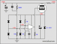
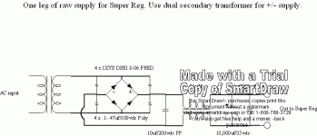
The super regulator as it was presented had limited data because of the design but nothing says that it can be done for any voltage and any current but if the requirements are more than 36 volts out and 1.5 A (1 A in real life) a redesign is necessary. There are a half dozen of avaible pcb's out there. The latest one comes from Taiwan but this one and noone else is rather well suited for higher power.
My idea was to design a regulator for
* 5-100 V out, 3 A min
* Normal 36 volts opamps, speed goal AD825 without oscillations
* LM431, LM329 and similar references
* LM338 preregulator, maybe
* Overvoltage protection for the LM338 and SR
* Short circuit protection (more advanced than usual, low loss)
* Maybe rectifier bridge and smoothing on the same pcb
* Fuse for incoming power
* Hole mounted parts mainly but possible to use SO08 opamps also
* Nice looking pcb
* Mainly "normal" parts, high industrial quality
Time frame: First half of 2006
At the moment I haven't dived into possible design problems concerning using opamps with less supply voltage than the output voltage.
I may drive this project according to my group buy guide lines.
How do you think it sounds?
Sounds very good. Is it too much of a stretch to ask for 250-300v tube-friendly variant? What are the issues with higher voltages? Just the size of electrolytics/resistors and the minimum track clearance?
i think you overstate the difficulty of building a hv regulator -- if it's opamp based you lift the "4" pin off the ground with a zener diode, protect the inputs with clamp diodes, etc., etc. use higher voltage components -- take a look at the Audio Research SP-10 which uses localized HV regulators for the phono and amplification stages.
in hv you are dealing with necessarily noisy thermionic devices anyway...
jack
in hv you are dealing with necessarily noisy thermionic devices anyway...
jack
analog_sa said:Sounds very good. Is it too much of a stretch to ask for 250-300v tube-friendly variant? What are the issues with higher voltages? Just the size of electrolytics/resistors and the minimum track clearance?
http://www.tubecad.com/2005/January/blog0031.htm
I actually think a 300V tube version is quite easy to make. I am working on a 2000VDC shunt reg using the same circuit.
Attachments
take a look at the Audio Research SP-10 which uses localized HV regulators for the phono and amplification stages.
The Jung regulator is way more sophisticated than the SP-10. It would be great if it becomes available as a high quality PCB suitable for high voltage as similarly to an SP-10 i feel each stage should get it's own regulator.
I actually think a 300V tube version is quite easy to make.
I am currently using something similar with good results. Still, building 6 of these critters may become a bit tiresome.
My limit for voltage is around 100 volts.analog_sa said:It would be great if it becomes available as a high quality PCB suitable for high voltage...
Making a wideband device which I plan the regulator to be is not easy. Compare our Taiwanese friend which has made a nice looking pcb but it's impossible to get it stable with AD825. He has made a minor error about the grounding and the bandwidth is heavily reduced. This may not be a problem if bandwidth wasn't the issue.jackinnj said:i think you overstate the difficulty of building a hv regulator -- if it's opamp based you lift the "4" pin off the ground with a zener diode, protect the inputs with clamp diodes, etc., etc. use higher voltage components -- take a look at the Audio Research SP-10 which uses localized HV regulators for the phono and amplification stages.
in hv you are dealing with necessarily noisy thermionic devices anyway...
So it may be easy, it may also be difficult....
Hey I was just wondering about a high-current super regulator!
Anyway, I'd be definitely be interested depending on final parts costs etc.
Also, if higher voltages became the sticky-wicket... I'd probably be interested in just a high-current version...
Anyway, I'd be definitely be interested depending on final parts costs etc.
Also, if higher voltages became the sticky-wicket... I'd probably be interested in just a high-current version...
our Taiwanese friend which has made a nice looking pcb but it's impossible to get it stable with AD825.
I had absolutely no problems with stability with 825.
peranders said:What is your application for "high current"?
Well high-current is probably going a bit too far. 🙂 But I have long wanted to try a super-regulator design with a Class-D amplifier. The problem has been that I don't want it to be terribly current limited and the 1-1.5A that most designs allow is just too low for me to be comfortable with. (Especially because I'd rather not be pushing the circuits tolerances). As far as voltage goes, you can do a lot with 20v (or 12!) in class-D so it isn't really a concern for me.
So perhaps a better wording would be "higher than normal" currents.
You maybe missed my specifications. You want less tan 36 volts so nothing is stopping you from from using an existing design. Do you know have a existing class D amp? Personally I think a class D amp should have a unstablised power supply.
PA:
I don't think that the super-reg design, in its unvarnished form, is appropriate for an HV supply -- it can oscillate if you don't compensate the feedback loop -- this was pointed out in the Audio Amateur articles and subsequent suggestions by Jung and others.
Any HV reg design should be vetted with a loop stability test.
P-A,
I need a version of this that will output + - 24VDC for a mic pre I'm working on. Each module consumes between 50-100ma. Is it stable enough for pro recording applications? What about using the LT-1085/1033 as the first stage regulators instead of the generic 317/337? Cost? I didn't see a GB price listed. Thanks.
Mike Morgan
If you want 24 volts there is no problem. The problem is more voltage out than the opamp can handle which is 36 volts or more.
50-100 mA, 24 volts, is no problem with the designs I already have.
Using a better regulator than the LM317 doesn't improve much because the major job is done by the super regulator but if it fits sure you can have other types.
This project hasn't reach the stadium of being a group buy. Now it's just checking the interest.
P-A,
Thanks for the reply. I checked out your website and may order from there. Have you tried Gary Galo's common mode choke in the raw supply? I usually build mine that way, with a small value (10uF) PP cap after the rectifiers, then into the CM choke, then a large electrolytic.
Mike
Thanks for the reply. I checked out your website and may order from there. Have you tried Gary Galo's common mode choke in the raw supply? I usually build mine that way, with a small value (10uF) PP cap after the rectifiers, then into the CM choke, then a large electrolytic.
Mike
No, any link?tenor39 said:Have you tried Gary Galo's common mode choke in the raw supply?
It was in a few issues of Audio Amatuer (now audioXpress) during the '90's. I have the issues, but I need to find the correct ones. I'll let you know.
Mike
Mike
- Status
- Not open for further replies.
- Home
- Group Buys
- High voltage, high current super regulator, possible group buy

