Hello, in my SE EL34 amplifier I have a pretty flat frequency response (within +/- 0.5dB +20Hz-20KHz, measured) and with full GNFB, I reach a minimum of 0.15% THD% at 1KHz @1W on 8.2 resistor.
But if I measure THD% at 50 or 100HZ, distortion rises to 1.5% @1W on 8.2 resistor. Why?
I don't understand if it is incorrect measurement or it is normal, or bad O.T. or something else.
Thanks
But if I measure THD% at 50 or 100HZ, distortion rises to 1.5% @1W on 8.2 resistor. Why?
I don't understand if it is incorrect measurement or it is normal, or bad O.T. or something else.
Thanks
How about posting a schematic of your amplifier?
What model of output transformer do you have?
What is the primary inductance of your output transformer?
How heavy is your output transformer?
Does your output transformer have an air gap?
That link you provided for the 2020 anniversary amplifier shows 2H and 2H for the output transformer. That is 8 Henry, since the inductance goes up at the square of the turns (two 2H is 4 times the 2H inductance if wound in series on the same transformer.
What is odd is that there is a center connection to that transformer primary.
8 Henry is 2500 Ohms at 50 Hz. That is a little bit low, and hard for an EL34 to drive.
How about posting a schematic of your amplifier?
What model of output transformer do you have?
What is the primary inductance of your output transformer?
How heavy is your output transformer?
Does your output transformer have an air gap?
That link you provided for the 2020 anniversary amplifier shows 2H and 2H for the output transformer. That is 8 Henry, since the inductance goes up at the square of the turns (two 2H is 4 times the 2H inductance if wound in series on the same transformer.
What is odd is that there is a center connection to that transformer primary.
8 Henry is 2500 Ohms at 50 Hz. That is a little bit low, and hard for an EL34 to drive.
Correct schematic.
The OT is original from a Boyuu A10 amplifier, all the rest I have changed.
The center connection was used for the UL connection which I don't use as I'm using a penthode connection only, because I like the sound (full sound).
So do you think the reason is the OT?
2H+2H is what I have measured with a LCR meter, may be reality is little different.
Total amplifier weight is 15Kg.
It is normal. Induction in the OT rises at low frequency, putting it close to saturation. It is part of the typical "rich tube sound".
So do you think the reason is the OT?
Exactly, too low primary inductance is the reason. I have observed this "feature" many times.
I fully agree with Icsaszar.
to ygg
Please take a look a Radiotron ( you can find on internet)
There is a beautiful paragraph about trafos.
The theory says that at mid frequency we can consider the OT trafo as ideal ( it is na semplification)
At low frequency the L of the trafo is in parallel with tube.
At high frequency the effect of the iron is very low but there is the parasitic component, C and L.
In the low frequency range the quality of the iron ( with the size) with the quality of the coils make a great difference specially with s.e. circuit where the dc is present.
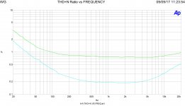
In attach a test made for one of the article I wrote for Audioreview in Italy.
The circuit is a s.e. with KT150 in triode mode
The Trafo is custom from F.I.A.T., the nucleus is double C laminated 0,1mm, good stuff.
The test is a THD vs frequency at 1 watt out and two bias current, 55 and 65 mA
Two lines the green is with 65mA and the blu at 55mA
With the 65 mA the THD at low freq. until 80Hz is lower because the Rp of the KT150 in less than a 55mA so the coupling with the L, in parallel, is better and the distortion is lower.
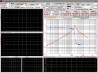
In the other diagram there ia a plot of the charateristic of the trafo under test.
It comes from a beta sw made by Montanucci at Audioreview.
At low frequency, 10Hz, you can read a impedance of 1,2 kohm ( about), at 20Hz about 3kohm until the peak at 2kHz where the inductive aspect of the trafo stop and became important the parasitic components, it became mainly capacitive.
As you understand if at low frequency the value of L is not enough you will have distortion.
To avoid this you must use high quality stuff.
This as general infos
Walter
Please take a look a Radiotron ( you can find on internet)
There is a beautiful paragraph about trafos.
The theory says that at mid frequency we can consider the OT trafo as ideal ( it is na semplification)
At low frequency the L of the trafo is in parallel with tube.
At high frequency the effect of the iron is very low but there is the parasitic component, C and L.
In the low frequency range the quality of the iron ( with the size) with the quality of the coils make a great difference specially with s.e. circuit where the dc is present.
In attach a test made for one of the article I wrote for Audioreview in Italy.
The circuit is a s.e. with KT150 in triode mode
The Trafo is custom from F.I.A.T., the nucleus is double C laminated 0,1mm, good stuff.
The test is a THD vs frequency at 1 watt out and two bias current, 55 and 65 mA
Two lines the green is with 65mA and the blu at 55mA
With the 65 mA the THD at low freq. until 80Hz is lower because the Rp of the KT150 in less than a 55mA so the coupling with the L, in parallel, is better and the distortion is lower.
In the other diagram there ia a plot of the charateristic of the trafo under test.
It comes from a beta sw made by Montanucci at Audioreview.
At low frequency, 10Hz, you can read a impedance of 1,2 kohm ( about), at 20Hz about 3kohm until the peak at 2kHz where the inductive aspect of the trafo stop and became important the parasitic components, it became mainly capacitive.
As you understand if at low frequency the value of L is not enough you will have distortion.
To avoid this you must use high quality stuff.
This as general infos
Walter
Attachments
Also, mains hum and rectifier harmonics exists at 50Hz and 100Hz, which may spoil the noise floor of measurements at those frequencies.
Even the best amplifiers on the market give a minimum THD% at 1KHz @1W and not at 20hz-20khz.
Its very difficult to measure distortion at 20hz, even if your amplifier is perfect. You need very expensive equipment, generator, distortion analyzer e.g
Its very difficult to measure distortion at 20hz, even if your amplifier is perfect. You need very expensive equipment, generator, distortion analyzer e.g
Its very difficult to measure distortion at 20hz, even if your amplifier is perfect.
I have not observed this. I use HP Audio Analyzer 8903B as a signal source and THD meter without difficulties at whole audio band.
What problems have you experienced ?
Agree with Artosalo
I have AP One and Ap Two
No problem, of course.
With a good sound card and a sw interface you can measure with a good resolution
Check a proper attenuator for the large signal, the sound card accept a low signal voltage
Walter
I have AP One and Ap Two
No problem, of course.
With a good sound card and a sw interface you can measure with a good resolution
Check a proper attenuator for the large signal, the sound card accept a low signal voltage
Walter
artosalo
I had never had the opportunity to use that equipment, its beyond my age. In my time distortion analyzers were completely analog and as far as I remember thy used a high Q stop filter for the measured frequency, usually 1khz. For20hz you can imagine how big and accurate the filter was going to be!
But even that computerized 8903B starts from 21 Hz 🙂
Anyway,
in my bench test I use analog audio generator and analoge dual trace oscilloscope up to 15Mhz. I cant afford an expensive analogue audio analyzer and I dont trust these computerised either,
because I Cant check them.
A good old sine generator with square wave output and a good oscilloscope does the job..
Best regards from Greece
This is no problem with budget 24bit USB soundcard.Its very difficult to measure distortion at 20hz, even if your amplifier is perfect. You need very expensive equipment, generator, distortion analyzer e.g
And if you do not trust this "modern digital stuff" you can do a loopback measurement. No rocket science at all!
Last edited:
bucks bunny
I'm from the old school!
As I said before,
real audio analog generator preferably with big variable a capacitor and a good analogue oscilloscope, you can still find it.
If you put your signal through a 24 bit digitizer, who cares about distortion?
In any case up to 3% you cant hear it.
And your loudspeaker has enormous distortion at low frequencies.
Can you check your speaker for distortion?
NO.
I see that you are from old school, believe me I am at a similar age than you are. Your equipment is outdated, besides step response and rf oscillations there is not much an analogue scope can reveal at audio circuitry. I am aware of the discrepancy between THD of electronic circuits and real speaker drivers. Following your argumentation, measuring amps distortion is useless.bucks bunny
I'm from the old school!
As I said before,
real audio analog generator preferably with big variable a capacitor and a good analogue oscilloscope, you can still find it.
If you put your signal through a 24 bit digitizer, who cares about distortion?
In any case up to 3% you cant hear it.
And your loudspeaker has enormous distortion at low frequencies.
Can you check your speaker for distortion?
NO.
THD of 3% can be heard easily depending on the spectral distribution of your signal so I would accept a limit of 0,1%, for instance.
Measuring THD below that limit is - just fun - and because we can make it😛
Yes
you can check all with a minimum stuff with reasonable prices.
And it is easy to check the 24 bit sound card simply putting a good signal in input and read the Thd (or FFT).
Then, after the check, you can measure what you want.
Walter
you can check all with a minimum stuff with reasonable prices.
And it is easy to check the 24 bit sound card simply putting a good signal in input and read the Thd (or FFT).
Then, after the check, you can measure what you want.
Walter
LF distortion is not hard to measure at all, you'll see THD graphs all over this site, since lots of people have computers and soundcards with reasonable or better ADCs. Old fashioned distortion analyzers take a long time for LF measurements, its true, but modern FFT based measurements are quick and straightforward.
- Home
- Amplifiers
- Tubes / Valves
- High THD at low frequency