Hello all,
I have started to build this HPA maybe with built in USB DAC and whammy style CRCRC PSU with 24V regulators (post 82) - List of best DIY Headphone Amplifiers
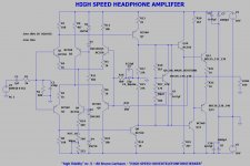
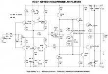
Also, I have attached my LT spice schematic.
I have a question on how to better match transistors - by pairs as suggested by W. Marshall Leach if its not possible to match all of them? I have various manufacturers BC 550/560 - Fairchild, Philips, ON - but pnp and npn have different Hfe...
q1,q3 - q5,q6 , - q2-q4 ?
thank you!
I have started to build this HPA maybe with built in USB DAC and whammy style CRCRC PSU with 24V regulators (post 82) - List of best DIY Headphone Amplifiers
Also, I have attached my LT spice schematic.
I have a question on how to better match transistors - by pairs as suggested by W. Marshall Leach if its not possible to match all of them? I have various manufacturers BC 550/560 - Fairchild, Philips, ON - but pnp and npn have different Hfe...
q1,q3 - q5,q6 , - q2-q4 ?
thank you!
Attachments
Last edited:
My most recent DIY headphone amp has a front panel switch that selects between "low gain" (+8 dB) and "high gain" (+16.3 dB). I find that these settings do a good job covering the range of sources I use, and the range of headphone sensitivities I use.
But the HPA schematic in post #1 appears to have a fixed gain setting of +21 dB. Why so high?
But the HPA schematic in post #1 appears to have a fixed gain setting of +21 dB. Why so high?
good question...I have experimented with class A SE one MOSFET HPA with gain 1 or 0,9x - sounds nice - 2H dominated .
Don't know - I probably like this symmetry and unnecessary complexity - but in this circuit if i increase feedback - i get worse THD numbers in LT Spice.
Don't know - I probably like this symmetry and unnecessary complexity - but in this circuit if i increase feedback - i get worse THD numbers in LT Spice.
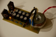
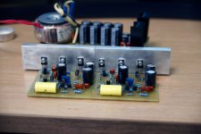
Now i have to think about the case in which to install this amp...
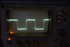
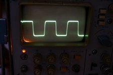
I attached square signal measurement - 20Khz and 50Khz (input filter approx. 1Hz - 200Khz in my amp)
The actual schematic also attached with with some component values adjusted to ones in my part box. Main changes - bias pot must be 1K. feedback el./bipolar can be 10 or 22 uf. I have 47uf in my box. Input cap can be 1uf.
Attachments

Osscar,
square wave measurements must be conducted without the input LPF (in your case without 220pF C2) and preferable at 100 kHz. With these 1k degenration resistors in the emitters of the differential pairs however, I'm afraid you'll not going to get the full schematic's potential.
square wave measurements must be conducted without the input LPF (in your case without 220pF C2) and preferable at 100 kHz. With these 1k degenration resistors in the emitters of the differential pairs however, I'm afraid you'll not going to get the full schematic's potential.
- Home
- Amplifiers
- Headphone Systems
- High speed headphone apmlifier