Are there any amplifier ICs that can handle +/-58V? I have a bookshelf stereo that is sentimental to someone, unfortunately since STKs arnt made anymore, they are hard to find unless chinese clones which are garbage. I tried, and it blew 3 times already.
So i am going to build an amp module retrofit, But i need to find a chip that can handle the rail voltages this thing puts out.
any ideas?
So i am going to build an amp module retrofit, But i need to find a chip that can handle the rail voltages this thing puts out.
any ideas?
I really don't understand what ST is trying to tell us here,
But this one: http://www.st.com/internet/com/TECHNICAL_RESOURCES/TECHNICAL_LITERATURE/DATASHEET/CD00001887.pdf
Can be supplied with 120V when there is no signal.
Easiest way to fix Your problem is in fact to rebuild Your power supply to a regulated one, with +/-60V? Will provide some loss, but it should be good still?
Probably easier than finding a genuine STK-amp I guess.
I tried building a transistor amp using the UPC2581 I had hanging around, following a sony schematic and turned out to be a disaster. distorted, oscillating like mad, etc...
I eventually got it tame, but it still had low level oscillation (couldnt hear) and it got hotter than hell.
So i gave up and want to go with a chip solution.
I eventually got it tame, but it still had low level oscillation (couldnt hear) and it got hotter than hell.
So i gave up and want to go with a chip solution.
http://www.edn.com/contents/images/45890.pdf
not saying you can do this trivially with power op amps but it may be one approach - need to heatsink the pass transistors, compensation may be squirrelly
would need to reduce the divider R values to supply worst case base current for the bootstrap Q
not saying you can do this trivially with power op amps but it may be one approach - need to heatsink the pass transistors, compensation may be squirrelly
would need to reduce the divider R values to supply worst case base current for the bootstrap Q
Are there any amplifier ICs that can handle +/-58V? I have a bookshelf stereo that is sentimental to someone, unfortunately since STKs arnt made anymore, they are hard to find unless chinese clones which are garbage. I tried, and it blew 3 times already.
Yes, some of the Chinese made STK are not exactly to Sanyo specs. They do blow up when you power up.
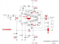
You can use the OEM STK4050V that I have. With the modifications I did, the STK4050V is stable. I tested them at +/- 65V for 200W full power. Should work at your voltages.
These mods are only applicable for my STK4050V.
Regards
Mike
Attachments
This unit used the STK-4221V, Yes and the junk ones do tend to spontaneously combust. Your STK is mono so it really isnt going to help considering the heatsink is very small, Fan cooled. Only enough room to fit 1 STK, I just barely managed to fit 4 TIP35/36 transistors on the heatsink, and they were packed side by side like sardines. Using TIP35/36 outputs with the UPC2581 worked ok, but it oscillated like a chinese bandwagon and the heatsink got way too hot way too quick.
I tried a couple already, one from MCM and one from Electronix online, they blew up. one on powerup, one after a little while.
I found an STK, which was way underpowered, but same pinout from an Optimus car amp from the mid 90s. Used that one, and it lasted a long time and eventually jamming it blew it.
So i have to find another option.. FAST.
Last edited:
Ah, i like the boostrapping idea (never understood that term, still dont, only in the digital world).
So, If i use the TDA7293/TDA7294, I could bootstrap these?
I read the document and the math is over my head. So, what type of transistors would i need? how much heat would they dissipate?
So, If i use the TDA7293/TDA7294, I could bootstrap these?
I read the document and the math is over my head. So, what type of transistors would i need? how much heat would they dissipate?
Bootstrapping - Wikipedia, the free encyclopedia
http://en.wikipedia.org/wiki/Bootstrapping_(electronics)
the added transistors are puling the chip amp power supply pins up, while the chip output is going up – hence the lifting itself by its bootstraps metaphor
some people mistakenly call it a cascode connection – but its not really that
other terms are cascade, totem pole – Leach Superamp is one example
Leach SuperAmp Plans
I wouldn't really offer it as a “quick fix” - there are enough questions, added parts that the integrated driver chip solution is in the same ballpark
the transistors have to pass all the current the chip amp supplies to the load, need enough gain (hfe) that the bootstrap resistors aren't too big of load and don't drop too much V supplying the base current for the Q
also need to be fast enough that they don't add phase shift to the chip amp feedback loop, destabilizing it – you probably want to run at higher than the chip amp min stable gain too
depending on divider ratio - say 1:1 then 1/2 the total V is dropped by the added Q so ~ 1/2 the total power added heat dissapation is needed, spread across both upper/lower Q
MJL3281/1302 are fast, but you may need to parallel – which then require emitter R – they are only fast up to ~4A per transistor
probably has to be buffered with a driver stage to keep the divider R power loss down to <10 W, the drivers need to be really fast too
MOSFET may be easier but you lose 4-6 V swing from each rail
Last edited:
This unit used the STK-4221V.....
You may want to consider the STK4241-ii. It is a stereo chip (120Wx2), pin compatible with the STK4221V and runs off +/-53V.
- Status
- This old topic is closed. If you want to reopen this topic, contact a moderator using the "Report Post" button.
- Home
- Amplifiers
- Solid State
- high rail voltage chip amps?