Hi.
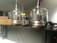
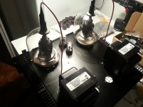
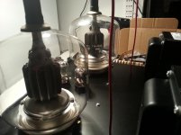
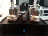
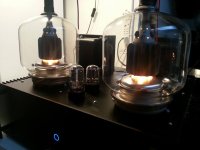
I have recently completed (well, almost) a gu46 based amplifier.
The specs are the following
6sn7 + 6sl7 (ccs laoded) two stage cap coupled driver
gu46 in pentode mode (1500v anode, 650v screen)
DC heating for all tubes
5k SE Hammond transformer (100mA bias per tube).
The gu46 works but I have a couple of questions.
1. the driver was designed based on the assumption that I would need GNFB. I have not had time to do a proper frequency sweep but I can tell bass rolloff is not that good. So I figure I would need some feedback.
Problem is I know very little of implementing GNFB. Would injecting signal through a voltage divider suffice? Do I need to add a capacitor to bypass the series resistor? Should the signal to inject be taken from the 4 ohm tap (used for speakers) or the 16ohm tap (currently not used)?
2. the gu46 filaments are DH of course. Unfortunately I was unable to score more than one switching transformer so I currently feed both tubes from one single supply. Is there are problem with this? Will the tubes crosstalk somehow or affect each other's behavior?
I have always used separate psus and haven't had the chance to test both channels of this new gu46 based amp at the same time so I figure I'd ask you guys while I can still find a solution.
Thanks
Attachments
I forgot to mention two things:
1. I am working towards obtaining at least 30W per channel of clean output from the Hammonds. I should be able to achieve that result with the current driver, load and B+. that is my target.
2. the gu46 are biased with a fixed negative voltage and the filaments pass through a 0.150ohm dropping resistor (8.5v at the terminals) in order to work within datasheet tolerance.
Thank you
Thank you very much. I'd love too but I don't have in digital form. I'll post one as soon as I can.
I only build large amplifiers using large transmitting tubes.
I only build large amplifiers using large transmitting tubes.
An externally hosted image should be here but it was not working when we last tested it.
An externally hosted image should be here but it was not working when we last tested it.
An externally hosted image should be here but it was not working when we last tested it.
Have even other stuff on my bench but I am concentrating on the gu46 at the moment ....
Need to get an answer of some sort before adding more components (which would make further changes very difficult).
Need to get an answer of some sort before adding more components (which would make further changes very difficult).
GMI90... :O
Re the original question. GNFB is often done by taking a resistor from the speaker output back to the cathode of the first stage. For best results, use the same tap that the speaker is connected to. You have to either remove the cathode bypass capacitor, or add another voltage divider resistor underneath it.
The feedback resistor should not be bypassed with a large capacitor as this would give the amp a gain of 1. The small capacitor you sometimes see across this resistor (10s or 100s of pF) is to help stability of the feedback loop. It's not always necessary, especially if the amount of NFB is modest.
Some people dislike GNFB and prefer local feedback in the output stage, with a large resistor from the output tube plate to the driver tube plate.
Since you are using fixed bias, there is no problem with the 2 channels sharing the same filament supply.
Last edited:
You will be fine with a single filament transformer for both channels. And, FWIW, you really don't need DC filaments on the non-directly-heated tubes.
You should have no difficulty achieving 30+ Watts at your chosen op points - however, I encourage you to consider a couple of things:
a) most (if not all) transmitting tubes benefit from low driver impedance: 6CK4, 6AH4, 6BL7 are a few octals that I would suggest vs the 6SN7...even better would be a pair of 2A3s.
b) similarly, these tubes like a low grid-to-ground impedance - therefore, direct-coupling or IT-coupling is recommended.
Best option in my opinion would be: 2A3 > 1:1 IT > GU46 with bias provided through the IT secondary.
I believe you will need to employ negative feedback. Start with a relatively high resistance - something like 15k (connected to the 16 ohm tap), and work your way down until it sounds right - a scope will be helpful - bear in mind, you're looking for bandwidth [while you are simultaneously trading away stability (and gain)].
After you've settled on a feedback resistor, you have the option of bypassing it with a capacitor. This offers stability, and can sometimes aid in high freq extension. [As Scopeboy says, the larger the feedback resistor (implying less NFB), the less necessary the cap bypass becomes.]
I generally use silver mica - my 'rule of thumb' for estimating the beginning size of this cap (in pf) is:
1,150,000 divided by the resistor value
For example, a 3k3 feedback resistor would call for a 350 pf cap (1,150,000/3,300 = 348.5).
Again, a scope is helpful...a schematic would also be helpful.
Hope this helps.
Last edited:
Hi.
The specs are the following
<snip>
Which one is driving the output tube, 6SN7 or 6SL7 ?
Your output stage is pentode connected and has high output impedance.
Therefore it is very likely that bass frequencies are attenuated to a certain extent. NFB, global or local would help.
The GNFB can be taken from 4 ohms tap or 16 ohms tap as well.
Your detailed questions about how to implement the GNFB would require big amount of basic NFB-theory. You should look for this information by searching the web.
GU46 requires some 15 A filament current. You mentioned that you supply both tubes from a common DC-supply (30 A). Can you describe this a bit more ?
I don't think the cross talk between tubes will be a problem. Some 35 dB is sufficient for full stereo image. And you can measure that very easily.
Feed the signal from one channel only and compare the L and R outputs.
A couple of additions to my earlier post:
1) please be aware NFB around an IT can be problematic - direct-coupling might be preferred.
2) I use stereo (shared between channels) DC filament supplies regularly - each channel has it's own pair of final inductors.
1) please be aware NFB around an IT can be problematic - direct-coupling might be preferred.
2) I use stereo (shared between channels) DC filament supplies regularly - each channel has it's own pair of final inductors.
Thanks to everyone for your answers. Here is the information you asked:
1. The dc supply is a meanwell switching unit. Seems to work well enough.
2. The 6sn7 is the first stage and the 6sl7 ccs loaded provides additional gain. The gu46 always work within a negative bias so i thought i could get away with a somewhat lighter driver. Input capacitance of the gu46 is not too terrible so it seemed worth a shot. The ccs is adjustable so i can use different tubes. 6bl7 perhaps?
3. I can add a nice little mosfet follower if you all think is a good idea. I just thought that it was like killing a fly with a hammer so to speak.
I am sorry if my questions are uneducated but my construction skills are much more developed than my theorerical basis. I can design a working amp but some aspects still elude me.
Working on the schematic right now.
Last edited:
An externally hosted image should be here but it was not working when we last tested it.
Coming alone. The xformers is a 800va unit. Plenty of headrom there.
Actually no, you do need to have separate heater supplies for dht tubes. Your filament/heater is actually your cathode. If you are running those on the same supply then you will have cross talk between the channels.
Think of it this way.... wold you tie the cathodes of 6l6 tubes together in a SE amp? Running both channels of a an amp from a single supply for dht tubes is exactly the same thing.
Use separate heater supplies and you will notice a big difference. Check the #26 preamp thread for info on dealing with dht tubes. It's totally applicable here.
Actually no, you do need to have separate heater supplies for dht tubes.
This is simply not accurate.
Actually no, you do need to have separate heater supplies for dht tubes. Your filament/heater is actually your cathode. If you are running those on the same supply then you will have cross talk between the channels.
The amount of this crosstalk should be measured first. If this is more than -30...-35 dB, then there is nothing to achieve with separate heater supllies.
2. The 6sn7 is the first stage and the 6sl7 ccs loaded provides additional gain.
Working on the schematic right now.
It would be logical to use the more "sturdy" tube (6SN7) to drive the output tube and use the 6SL7 at the front.
- Home
- Amplifiers
- Tubes / Valves
- High power GU46 SE amplifier - help with certain issues