Hi Hollowman
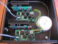
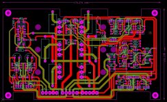
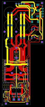
Looks very neat -- Just a point on construction - It may benefit to have the incoming power to take the shortest possible journey -- it looks like the cord travels all the way around the box. Otherwise it could be more opportunity for interference to inject into the signal paths, creating that little background bzzzzz nobody likes..😉
Does the model number suggest the power? 120Watt?
Have you tested it's performance? It's nicely laid out. I suppose one could configure it in conventional dual mono with two transformers as the separate power supplies exist -- but I realise this hikes the cost up
Also it looks like most of the items in contact with the heatsink are TO220 style
is this correct?
Thermal management is improved if the surface of the heatsink is used to better effect - efficient use of the flat area of "real-estate" that can be used to distribute the thermal load. - rather than grouping all the components together in one corner.
Nice practical looking design that could be made modular so that it could be constructed into a 5x or 7x amplifier variant for THX, DTS and DOLBY surround fairly easily
Last edited:
Don't rush, there's room for all!
I will be continuing with my new project, to clone a AW250 or AW400, the aim being to make electrocompaniet engineers blush on sighting!
I will be continuing with my new project, to clone a AW250 or AW400, the aim being to make electrocompaniet engineers blush on sighting!
Hollow, sorry Im away from home and terribly busy at the moment, I will get a friend of mine to visit my home PC and email me a copy of the schematic which I will then send to you.
Hello Hollow_man,
Is it an idea, since you "copy" the more modern versions, to create the never produced
"Perfect Two-Channel" ? That would be a challenge 🙂
Without cascode-follower: roughly 35Watts(8ohm), regulated and separated power supplies, different transistors.
We are 35 years after date, there are transistors out since then that could do the job done the right way 🙂 I still want to do it as I have it almost complete on drawing. ..
the original drawings I mean (!) It does run hot 🙂
Hello Sorscha,
I am not attempting to clone the 'the two channel amplifier'. My clone is based on quite late electro designs, it does not use cascoded stages, nor does it use outdated output transistors.
If you read my earlier posts again you you will see that I have already cloned an AW120-ish, circa 2002, and I am now attempting to expand this to 250-400Watts. But it's been f***ing hard work so far and nobody bothered to help with the EC schematics.
Last edited:
h_a,
my initial purpose for posting this thread was to source the AW250 schematic, which other diy_audio members claim to own, and then share ideas and information on cloning it. However, it seems that either I am not likable enough to be the priveledged receipient of the said schematic, or it is more of a ghost schematic.🙂
Either way, I do apologize but for me this thread is henceforth closed.
Oh, I see I misunderstood you, sorry.
I just looked at Jan's site,
Categorized Schematics and Service Manuals for free download A-C
and at least some schematics up to AW120 are available. Just in case you didn't know yet.
I just looked at Jan's site,
Categorized Schematics and Service Manuals for free download A-C
and at least some schematics up to AW120 are available. Just in case you didn't know yet.
Hi.
Nice work Hollow_man !
This is my first post on an internet forum ever.
I have one AW100DMB and one AW250DMB in my triamp system allready,so I have to build a pair of theese, because I love the way theese amps play MUSIC.
Now some questions:
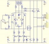
1 Are Q7 and 8 on the input stage your own modification, and have you listend to it ?
Any values for R15,16,17,18 ?
2 Is it OK for the input stage to drive both output stages ? It's a good idea to do it this way.
3 What are the rails (VCCand VDD), and what VA rating are you going to use ?
4 I will use SA1837/ SC4793 instead of SA1358/SC3421. What do you think about that ?
(lower fT, but same cob)
I hope you don't kill the tread !
Bridging is a good way to build powerful amps in my opinion.
I have downscaled and bridged the JLH classAB amp to be driven by 12V solarpower in my hollyday house, to get more power from that low voltage. (I know I could buy a car-amp)
Sorry if my english isn't flawless.
Nice work Hollow_man !
This is my first post on an internet forum ever.
I have one AW100DMB and one AW250DMB in my triamp system allready,so I have to build a pair of theese, because I love the way theese amps play MUSIC.
Now some questions:
1 Are Q7 and 8 on the input stage your own modification, and have you listend to it ?
Any values for R15,16,17,18 ?
2 Is it OK for the input stage to drive both output stages ? It's a good idea to do it this way.
3 What are the rails (VCCand VDD), and what VA rating are you going to use ?
4 I will use SA1837/ SC4793 instead of SA1358/SC3421. What do you think about that ?
(lower fT, but same cob)
I hope you don't kill the tread !
Bridging is a good way to build powerful amps in my opinion.
I have downscaled and bridged the JLH classAB amp to be driven by 12V solarpower in my hollyday house, to get more power from that low voltage. (I know I could buy a car-amp)
Sorry if my english isn't flawless.
Hello Styrkv,
thank you for your kind words. At some point I felt like killing the thread, but in the end I could not keep my hands from it😎.
Taking each of your points in turn.
1. Yes and no, I have seen EC use them in one their preamps. They are current sources for the input buffer fets and can be fitted or omitted as desired on the same pcb with no ill effects. I have no idea how they sound.
Please see the attached schematic for some starting values that will yield currents equal to their resistive counterparts.
2. I think it is a good idea to have a common phase splitter, in the sense that both bridge halves will receive identical signals. This of course, provided that voltage drive is utilised at the interface, hence the circuit split after the emitter followers and not the following transimpedance stage.
3. Vcc of the order of 33V, Vdd 43V, 650VA per channel, for 250Watts at 8 Ohms. With 12 output devices I believe the design can be pushed to 400W, in which case you would require rails of 42 and 52V respectively at 1KVA.
4. I though about using them too, but there is no need power consumption-wise, due to the bridging. Why have the extra capacitance though? Be aware that pinout is different.
Alas, I now need a sponsor to pay for all those pcbs, metalwork, etc!😀
Attachments
- Status
- Not open for further replies.
- Home
- Amplifiers
- Solid State
- High-Power Electrocompaniet clone