I really like the Eminence KL3012LF as a pair per side. They settle in at an Fs of 35 Hz once run in and have quiet motors despite being 94 dB @ 2.83V sensitivity per driver. As a pair thats close to 98 dB @2.83V and ends up at about 94 dB with BSC. You get an F-3 of about 35 Hz this way with a healthy SPL capability and 800W of thermal capacity in a ported box. A pair of SB34NRXL may also be enough for 95 dB sensitivity @ 2.83V and shouldn't need much BSC. I'd probably choose the SB34NRXL if crossing betwen 300 - 500 Hz. For a 500 Hz crossover to M74A I'd be more tempted by the snappier KL3012LF. Its a great ported box driver that can take alot of power and deliver most of it in clean acoustic output.

There is a couple of Dueland 3 way options in the Vituix library under Active, they are pretty close approximations. There are also Dueland target slopes in the optimizer.Regarding the Duelend, are you aware of a resource or documentation which illustrates how to realize this filter topology using standard IIR or analog building blocks?
For the elliptic mid to tweeter, there is also another way that I simulated for my own M74 and shallow waveguided SB textreme tweeter based on the Elsinore scheme.
https://www.diyaudio.com/community/...es-3-dome-midrange-lineup.380200/post-7486594
One of the things I do like about it is that the narrow vertical response is on the side towards the floor. Having a big hole vertically right above the normal listening axis kind of forces you to always be sat in the money spot.
Last edited:
Of course, as DIYers, we are free to do as we please, and curiosity kills the cat, so some of us have built oversized speakers 5-6’ tall, 2 man lift/‘needs piano mover’ speakers to satisfy that curiosity. 🤪😂🙈
Yes indeed. My first box was 6' tall of double thickness MDF, ridiculously heavy. I didn't bother putting in the drivers, because at 100 kG (220 lbs) sans transducers or crossover I didn't feel like having the first earthquake splat me like a Looney Tunes coyote under a rock.
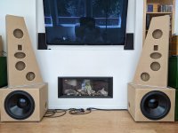
The current thinking is something like the image below (not in the target location). The subs are 45 kG (100 lbs) each while the mid-high panels will be 35ish kG (75-80 lbs) fully populated. The whole thing is a one man move, easier with a hand truck.
Attachments
I think the (bit of a) narrow baffle isn’t helping there.PS: The 2K off axis rising in both looks like trouble to me.
Thanks to @fluid - your suggestion to add a notch to make the 2nd order slope of the woofer more elliptical works well.
Here is one version that looks good

This prompted me to try some other techniques to flatten out the directivity bump at 500 Hz. This next filter uses an offset 2nd order slope. The midrange is 500 Hz Q=0.67 and the woofer is 300 Hz Q=0.6. This introduces a deliberate phase mismatch between the two drivers of about 40 degrees. Some EQ is used to bring everything back to flat.

Both of the above look pretty good for a "proof of concept" simulation. Real driver responses will be different than these idealized responses, so there is a level of uncertainty in these simulations. Nonetheless, these sims give me confidence that an acceptable DI curve will be achievable with this baffle layout.
There is still a bump in off-axis horizontal response at about 2k. My opinion is that this is caused by the flat baffle area around the midrange. Due to the tapering of the bevel, the midrange has 40 mm of flat baffle on each horizontal side before the bevel begins. The bevel around the midrange is only 42 mm wide compared to 75 mm wide at the tweeter.
If the bevel was not tapered, but instead remained 75 mm wide from top to bottom, the midrange edge distance would be just 7mm instead of 40 mm, a significant reduction in flat baffle area.
This is how that baffle simulates:

I am showing a filter which uses an offset 2nd order rather than an elliptical/notch style, but both styles achieve a similar result. As can be seen, the horizontal polar response is much better behaved in the 500 - 5k range. The 500 Hz directivity bump is just visible, but it is less than 0.6 dB, i.e insignificant.
So what would this speaker look like? If the 75 mm wide bevel was carried through from top to bottom, there would not be enough baffle width to accommodate the woofer. One idea would be to end the bevel just above the woofer. An angled tapered transition would be necessary to mate the square woofer box to the beveled midrange tweeter baffle, and I have some ideas on that.

j.
Here is one version that looks good
This prompted me to try some other techniques to flatten out the directivity bump at 500 Hz. This next filter uses an offset 2nd order slope. The midrange is 500 Hz Q=0.67 and the woofer is 300 Hz Q=0.6. This introduces a deliberate phase mismatch between the two drivers of about 40 degrees. Some EQ is used to bring everything back to flat.
Both of the above look pretty good for a "proof of concept" simulation. Real driver responses will be different than these idealized responses, so there is a level of uncertainty in these simulations. Nonetheless, these sims give me confidence that an acceptable DI curve will be achievable with this baffle layout.
There is still a bump in off-axis horizontal response at about 2k. My opinion is that this is caused by the flat baffle area around the midrange. Due to the tapering of the bevel, the midrange has 40 mm of flat baffle on each horizontal side before the bevel begins. The bevel around the midrange is only 42 mm wide compared to 75 mm wide at the tweeter.
If the bevel was not tapered, but instead remained 75 mm wide from top to bottom, the midrange edge distance would be just 7mm instead of 40 mm, a significant reduction in flat baffle area.
This is how that baffle simulates:
I am showing a filter which uses an offset 2nd order rather than an elliptical/notch style, but both styles achieve a similar result. As can be seen, the horizontal polar response is much better behaved in the 500 - 5k range. The 500 Hz directivity bump is just visible, but it is less than 0.6 dB, i.e insignificant.
So what would this speaker look like? If the 75 mm wide bevel was carried through from top to bottom, there would not be enough baffle width to accommodate the woofer. One idea would be to end the bevel just above the woofer. An angled tapered transition would be necessary to mate the square woofer box to the beveled midrange tweeter baffle, and I have some ideas on that.
j.
Don't be afraid to up the Q or gain on the notch or to add another first order filter higher in frequency to drop the output of the woofer if it needs it.Thanks to @fluid - your suggestion to add a notch to make the 2nd order slope of the woofer more elliptical works well.
I would reserve some judgement on the cause based on a flat piston simulation, a real M74 does not seem to be prone to being difficult with a bit of flat baffle area around it. As it radiates widely in all directions the tapering of the bevels below becoming quite small may also play a part, that could also be why your second design looks better in that regard.There is still a bump in off-axis horizontal response at about 2k. My opinion is that this is caused by the flat baffle area around the midrange.
If you really prefer the look of the first one I wouldn't count it out before making a mock up to see what you get in reality.
Yes - that's true!Understand, thanks for reply!
Regarding the Hypex DAC: I've read somewhere that the current Fusion DSP module bundles two of the AKM AK4454 DAC channels for the tweeter channel to improve SNR.
If you're thinking of notching the woofer cutoff response, this paper may be of interest:
https://purifi-audio.com/blog/app-notes-2/low-distortion-filter-for-ptt6-5x04-naa-11
https://purifi-audio.com/blog/app-notes-2/low-distortion-filter-for-ptt6-5x04-naa-11
Yepp, my current active speakers have also passive series notch on the breakup resonance of the alu mid cone.
The M74A is predestined for such a treatment - it might help to suppress some resonance echoes in the distortion FR:

The M74A is predestined for such a treatment - it might help to suppress some resonance echoes in the distortion FR:
Would it be a huge inconvenience to you to also show a 4th order version for comparison?
Here is the baseline with all 2nd order crossovers
Here is the result with 4th order crossovers. All I changed was the highpass and lowpass filters, no other changes to EQ were done, which means that some minor optimization might make the on-axis or power response a bit smoother. However, the DI curve would not be affected by any changes in EQ, and at this stage of the design, the DI curve is the primary focus.
The LR4 at 3.5k works out ok, but only with real driver measurements would we know whether 2nd order or 4th order is better. The arrow-head shape of the vertical polar response is still present. At 500 Hz, the LR4 creates a directivity bump, which may or may not be important. But the biggest drawback to the 500 Hz LR4 is the abrupt change in group delay near 500 Hz.
In other projects, I noticed a significant subjective preference for a 300 Hz 2nd order crossover compared to a 300 Hz 4th order crossover. The on-axis curves were identical, and power response was only slightly different. The main difference was the group delay between 100-1k. So i am naturally inclined to use 2nd order for the lower crossover.
j.
In terms of looks, I don't have a preference. The first one with tapered bevels looks more like a commercially available speaker, and more like what might be seen in a professional environment. The second is more unique look.If you really prefer the look of the first one I wouldn't count it out before making a mock up to see what you get in reality.
The baffle for this speaker will be made from solid wood, laminated in alternating layers of grain direction. This may include the woofer section of the baffle, or it may be only the mid-tweeter section. The reason for this is to allow me to round and profile the baffle edges to remove sharp corners, yet still maintain the polished wood finish I like. Working with veneer is limiting, because it can only follow a radius across the grain, not with the grain, and compound curves are not possible. The flat panels (sides and top) will be veneered.
With that in mind, the second (non-tapered bevels) is slightly easier to construct, and has more flexibility in rounding the bevels to more approximate a large radius. I will probably mock up this second configuration first, and if it does not give a good result, then I will try the tapered bevel.
After measurements, I'd like to see mid's distortion with LR2@500Hz. Perhaps it could be pushed to 400Hz, that would help quite a lot for DI
Another possibility might be to use flat baffle with horizontally offset mid and tweeter. Small asymmetry of off-axis is not really bad IRL
https://www.audioholics.com/tower-speaker-reviews/yamaha-ns-5000
http://www.troelsgravesen.dk/Yamaha-NS1000.htm

Another possibility might be to use flat baffle with horizontally offset mid and tweeter. Small asymmetry of off-axis is not really bad IRL
https://www.audioholics.com/tower-speaker-reviews/yamaha-ns-5000
The very intersting thread titled "Are they all badly designed?" got me thinking again about the Yamaha NS-5000s and all the areas of performance they seemed to take into consideration....and one big one that they did not. There's a nicely constructed cabinet to avoid box/panel resonance, fancy custom drivers attemting to reduce both cone resonance AND backwave resonance, and that tuned pipe resonator device. Lots of concentration on various resonant "gotchas", but then they do something so 70's and use a very high crossover point btw the mid and tweeter AND have a large physical...
- studiotech
- Replies: 21
- Forum: Multi-Way
http://www.troelsgravesen.dk/Yamaha-NS1000.htm
Last edited:
My current plan is to use a passive notch filter in series with the M74A and the woofer, and possibly the tweeter.The M74A is predestined for such a treatment - it might help to suppress some resonance echoes in the distortion FR:
I can't make my mind up whether I prefer an old school looking classic 3 way baffle like the NS-1000 or something like Joachim Gerhard's Kronos.In terms of looks, I don't have a preference.
No effort is made to smooth the junction between the upper panel and bass cabinet, visually I like that.

I am making progress on fabricating a prototype test baffle for the M74A. In earlier projects, I would often use XPS foam board for prototyping, but due to the kind of beveling I am planning, there are advantages to using plywood.
The mid-tweeter baffle is rectangular, 286mm (W) x 363mm (H). The midrange is located 273mm down from the top edge. A 70 mm wide bevel is applied to the sides and top. This bevel has a compound angle of 22.5 and 45 degrees. One of the reasons to use a plywood test baffle is to develop the jig/saw-setup that can be used to cut this edge. I learned a few things, and the production jig will be different.


The mid-tweeter baffle is rectangular, 286mm (W) x 363mm (H). The midrange is located 273mm down from the top edge. A 70 mm wide bevel is applied to the sides and top. This bevel has a compound angle of 22.5 and 45 degrees. One of the reasons to use a plywood test baffle is to develop the jig/saw-setup that can be used to cut this edge. I learned a few things, and the production jig will be different.
Yes, wide dispersion is the goal.
The 22.5 degree angle is cut first, and I had enough blade depth that I should have been able to make the full cut. But the nature of the setup applied a pressure on the offcut piece that was binding the blade the deeper I cut. The machine warned me of this as I was attempting the final through-cut (it is always wise to listen to the machine when it warns you). So I had to do the final cutting with a hand saw, and the overall cut quality was a bit rough and uneven. Acoustically this is no problem, but it is something I will have to address before I make the real cabinet.
The next step is to make a flat plate baffle to simulate the lower (woofer) section. I will first test the midrange with no transition, and I expect this will give me a reflection. Then I will try a couple of ideas for a smooth transition.
j.
Did you find the first cut where the piece runs between the saw's fence and the temporary fence a problem? It looked a like the cutoff might be pinched by the blade and the temporary fence. Maybe because it wasn't a through cut there isn't a chance of a kickback. The second cut using the jig riding in the miter slot looked very safe. Having caught a cutoff in the gut once I hope to never experience a kickback again.
Yes, I did find that a problem. That is why I wroteDid you find the first cut where the piece runs between the saw's fence and the temporary fence a problem? It looked a like the cutoff might be pinched by the blade and the temporary fence.
But the nature of the setup applied a pressure on the offcut piece that was binding the blade the deeper I cut. The machine warned me of this as I was attempting the final through-cut (it is always wise to listen to the machine when it warns you). So I had to do the final cutting with a hand saw,
I started the cut with the blade extended about 1/2 inch, and I kept proceeding with deeper cuts. When I started the final thru-cut, I had could tell I had binding, so I backed up.
For the actual cabinet, I will build a jig which fully supports the baffle from the left side. My tenoning jig does not have enough range of adjustment to make the 22.5 degree cut, although it works great for the second 45 degree cut. I need to make a jig which mimics the tenoning jig.
- Home
- Loudspeakers
- Multi-Way
- High Performance 3-way based on Bliesma M74A