I'm trying to understand electronics a bit better and have been reading the guides in radio-electronics.com, which i think is a fantastic site for noobs like myself.
This extract has been taken from radio-electronics.com and has been written by Ian Poole.
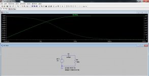
AC coupling the non-inverting op-amp circuit
In most cases it is possible to DC couple the circuit. However in this case it is necessary to ensure that the non-inverting has a DC path to earth for the very small input current that is needed. This can be achieved by inserting a high value resistor, R3 in the diagram, to ground as shown below. The value of this may typically be 100 k ohms or more. If this resistor is not inserted the output of the operational amplifier will be driven into one of the voltage rails.

Basic non-inverting operational amplifier circuit with capacitor coupled input
When inserting a resistor in this manner it should be remembered that the capacitor-resistor combination forms a high pass filter with a cut-off frequency. The cut-off point occurs at a frequency where the capacitive reactance is equal to the resistance.
My question is how do you determine the cut of frequency by adjusting the combination of R3 and C1?
Bibs
This extract has been taken from radio-electronics.com and has been written by Ian Poole.
AC coupling the non-inverting op-amp circuit
In most cases it is possible to DC couple the circuit. However in this case it is necessary to ensure that the non-inverting has a DC path to earth for the very small input current that is needed. This can be achieved by inserting a high value resistor, R3 in the diagram, to ground as shown below. The value of this may typically be 100 k ohms or more. If this resistor is not inserted the output of the operational amplifier will be driven into one of the voltage rails.
Basic non-inverting operational amplifier circuit with capacitor coupled input
When inserting a resistor in this manner it should be remembered that the capacitor-resistor combination forms a high pass filter with a cut-off frequency. The cut-off point occurs at a frequency where the capacitive reactance is equal to the resistance.
My question is how do you determine the cut of frequency by adjusting the combination of R3 and C1?
Bibs
>My question is how do you determine the cut of frequency by adjusting the combination of R3 and C1?
Consider the opamp draws no current from its "+" input, thus you can do the calculation without the opamp, and it is a simple RC highpass. Pole is at frequency giving equal impedance to R and C.
Consider the opamp draws no current from its "+" input, thus you can do the calculation without the opamp, and it is a simple RC highpass. Pole is at frequency giving equal impedance to R and C.
so if i have done the maths right then 100k resistor and a 0.47uf cap would work out to 29.5 ish htz
still confused. in the schematic i'm working from 100k and .47uf cut the low frequency.
oohh wait on the schematic i'm looking at there is another resistor just after C1 with a value of 470R.
looks like i'll have to do more reading. thought i was getting there.. lol
oohh wait on the schematic i'm looking at there is another resistor just after C1 with a value of 470R.
looks like i'll have to do more reading. thought i was getting there.. lol
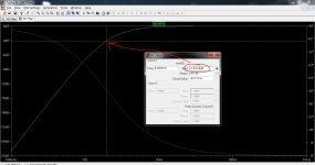
A 0.47uf cap with a 100K to ground forms a "first order" high pass filter. The "cut off" frequency is when the output voltage fall to 0.707 of the input voltage and is given by the formula in post #2
The 29.5Hz you worked out suggests a wrong decimal and you not taking the reciprocal of the calculation (dividing it into 1)
The 29.5Hz you worked out suggests a wrong decimal and you not taking the reciprocal of the calculation (dividing it into 1)
oohh wait on the schematic i'm looking at there is another resistor just after C1 with a value of 470R.
A resistor after the filter will have minimal effect because the input impedance of the amp is so high.
yes i was doing the maths wrong.
so can just go ahead and ignore the 470R while doing the figures?
so can just go ahead and ignore the 470R while doing the figures?
i'm only asking as i would like to stop anything under 20hz ish from a turntable entering the amp output.
i'm only asking as i would like to stop anything under 20hz ish from a turntable entering the amp output.
A rumble filter you mean. Well a 0.082uf would roll off around 20Hz. Rumble is very low though so perhaps a bit of experimentation looking at the speaker cone as you play a record. I'm not a vinyl expert I'm afraid.
hmm. it might be a placebo but i'm sure i can hear a difference between .47uf and 2.2uf (only available caps i have to test) when listening.
hmm. it might be a placebo but i'm sure i can hear a difference between .47uf and 2.2uf (only available caps i have to test) when listening.
Oh heck 😀 Listening tests (and particularly caps) is something we've been doing rather a lot of on the forum lately... what can I say... you must trust what you hear.
think i'll stop pizzing about and live in ignorant bliss 😀
seems to have worked most of my life 😛
my brain is hurting.
seems to have worked most of my life 😛
my brain is hurting.
Lol OK 🙂
You might find this interesting as it shows the practicalities of a filter.
Subsonic / Rumble Filter for Phono preamps and Sub-Woofers
You might find this interesting as it shows the practicalities of a filter.
Subsonic / Rumble Filter for Phono preamps and Sub-Woofers
- Status
- Not open for further replies.
- Home
- Amplifiers
- Chip Amps
- high pass filter in non inverting op-amp circuit