I'm rebuilding an old Zenith stereo console, a 1969 Y960, their highest-end unit at the time.
It includes a turntable with a ceramic cartridge. Because the particular turntable/cartridge is considered quite good, (it's a Zenith 2G Professional Turntable) and is aesthetically awesome, I would like to keep it installed in the console, but I need it to play nice with modern electronics. The original amp/preamp is gone, and I'll be installing new components.
I'm very much a newbie in this area of audio (I'm mainly a speaker building guy), but my research indicates these ceramic cartridges have a high output and require a high impedance input to load them properly. So they don't work with a regular modern phono-stage.
This turntable's cartridge is rated at 350 mV per channel at 1 kHz and was connected to the attached preamplifier circuit, which was designed by Zenith specifically for this turntable.
My questions:
1.) How best can I replicate the original circuit's loading?
2.) Am I right in calculating the input impedance of the preamp at around ~1M ohm? It's been a long time (since high-school), and I find the schematic mildly confusing. The transistors used each have a current gain of 100.
My thought was to attach the turntable to a buffer. Perhaps a simplified B1 with input impedance modified to match the original circuit, then in to a preamp. It doesn't need much gain.
Thoughts please!
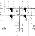
*Note: I cut out most of the complicated switch diagrams that get the phono input to the preamp, but included the one section because it shows a 2.2M resistor connected across the turntable's two channels at the output.
It includes a turntable with a ceramic cartridge. Because the particular turntable/cartridge is considered quite good, (it's a Zenith 2G Professional Turntable) and is aesthetically awesome, I would like to keep it installed in the console, but I need it to play nice with modern electronics. The original amp/preamp is gone, and I'll be installing new components.
I'm very much a newbie in this area of audio (I'm mainly a speaker building guy), but my research indicates these ceramic cartridges have a high output and require a high impedance input to load them properly. So they don't work with a regular modern phono-stage.
This turntable's cartridge is rated at 350 mV per channel at 1 kHz and was connected to the attached preamplifier circuit, which was designed by Zenith specifically for this turntable.
My questions:
1.) How best can I replicate the original circuit's loading?
2.) Am I right in calculating the input impedance of the preamp at around ~1M ohm? It's been a long time (since high-school), and I find the schematic mildly confusing. The transistors used each have a current gain of 100.
My thought was to attach the turntable to a buffer. Perhaps a simplified B1 with input impedance modified to match the original circuit, then in to a preamp. It doesn't need much gain.
Thoughts please!
*Note: I cut out most of the complicated switch diagrams that get the phono input to the preamp, but included the one section because it shows a 2.2M resistor connected across the turntable's two channels at the output.
Attachments
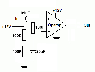
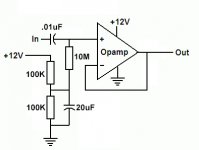
Given the high value bias resistors needed this might be a job for a JFET input opamp like TL072. A simple unity gain follower ought to do it, using 1M bias resistors to the non-inverting inputs. That substitutes for the two emitter-follower stages in that preamp.
> input impedance of the preamp at around ~1M ohm?
The ceramic needle needs a high Z for deep bass, but there's no "magic value". Getting very very high Z out of Ge parts is tough, and the two stages hint they aimed well over 1Meg. As Mark says, today the TL072 fits the bill nearly ideally. Certainly unity-gain. 10Meg after the coupling cap is fine with the '072. If you can sport a bipolar supply on the '072 then you do not need coupling caps. 12V supply seemed ample then. Considering hotter lathes in the 1970s, a +/-15V supply could be argued. Don't forget the 100pFd to AC ground, though this may be to tame the Ge parts when the cart is not connected.
The ceramic needle needs a high Z for deep bass, but there's no "magic value". Getting very very high Z out of Ge parts is tough, and the two stages hint they aimed well over 1Meg. As Mark says, today the TL072 fits the bill nearly ideally. Certainly unity-gain. 10Meg after the coupling cap is fine with the '072. If you can sport a bipolar supply on the '072 then you do not need coupling caps. 12V supply seemed ample then. Considering hotter lathes in the 1970s, a +/-15V supply could be argued. Don't forget the 100pFd to AC ground, though this may be to tame the Ge parts when the cart is not connected.
For thatZenith "floating" ceramic cartridge to play into a line input, rig a 470K resistor paralleled with a 250Pf cap on the "hot side" lead.
You can "tweak" the cap value to suit - less will give less treble boost.
You can "tweak" the cap value to suit - less will give less treble boost.
I'm looking at the datasheet for the TL072, and it doesn't seem to work in unity gain with the voltage I'm dealing with (350mV). See page 29 and 30. Or am I misunderstanding?
http://www.ti.com/lit/gpn/TL072
Sorry if that's a dumb question. As I mentioned, I'm new at this.
I'm probably entirely wrong, but I don't understand how the input impedance of the original circuit is much higher than 1M. Can you explain what made you say that so I can understand?
http://www.ti.com/lit/gpn/TL072
Sorry if that's a dumb question. As I mentioned, I'm new at this.
PRR said:...and the two stages hint they aimed well over 1Meg.
I'm probably entirely wrong, but I don't understand how the input impedance of the original circuit is much higher than 1M. Can you explain what made you say that so I can understand?
Maybe this is a whole different 'class' of ceramic cartridge .. Or maybe its just my hi-fi snobbery creeping in -- after all, it was already starting to firm up when this console was brand new .. But the vinyl that I still have isn't chewed up enough that I'd be willing to subject it to ceramic cartridge wear and tear. Maybe it'd be worth it to consider tacking on a bit of a counter weight and lash-up a middle-grade MM cartridge instead. Of course, then you'd need RIAA and a bit more gain.
Surely the original circuit wouldn't be worth any more than a cursory glance, since there are so many far better/simpler/cheaper options to choose from today.
But one more aside -- those voltages look more like silicon than germanium.
Regards
Surely the original circuit wouldn't be worth any more than a cursory glance, since there are so many far better/simpler/cheaper options to choose from today.
But one more aside -- those voltages look more like silicon than germanium.
Regards
The page 29 and 30 mentions of 'voltages to avoid' are talking about DC levels, not signal levels. If you stick with the ~12V supply, you'll want to bias the TL072 to around the midpoint, just as it is in the original design. Your 350mV signal won't give it any grief at all.
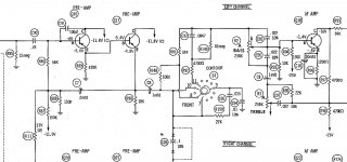
The very high input impedance of the original circuit stems from the bias node being driven by the output through C7. The 150k resistor pair, R87 and R88, sets the DC operating point, but then that node sees almost the full input signal swing from the cascaded emitter followers. The effect is to cause the 56k resistor to appear to the input signal as if it had a much higher value.
The very high input impedance of the original circuit stems from the bias node being driven by the output through C7. The 150k resistor pair, R87 and R88, sets the DC operating point, but then that node sees almost the full input signal swing from the cascaded emitter followers. The effect is to cause the 56k resistor to appear to the input signal as if it had a much higher value.
Maybe this is a whole different 'class' of ceramic cartridge... But the vinyl that I still have isn't chewed up enough that I'd be willing to subject it to ceramic cartridge wear and tear.
It actually is! Or at least that's what Zenith's vintage sales literature tells me. So it must be true. Haha!
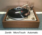
But seriously, it actually is. Zenith spent a good long time developing this table and cartridge in a joint effort with CBS and EV. It is widely considered quite good sounding (for what that's worth), and on-par with mid-range MM cartridges. It uses only 2 grams of tracking weight, which I understand is pretty decent.
There are videos on YourTube of Mike Wallace explaining all of this and throwing the needle of a MicroTouch 2G across some records. If you want a fun flashback, search for Zenith MicroTouch 2G on YouTube.
But one more aside -- those voltages look more like silicon than germanium.
I think they are silicon, but I have the verify the part numbers. They are cut off in my SAMS manual.
The page 29 and 30 mentions of 'voltages to avoid' are talking about DC levels, not signal levels. If you stick with the ~12V supply, you'll want to bias the TL072 to around the midpoint, just as it is in the original design. Your 350mV signal won't give it any grief at all.
Ah! Of course. I'm new, but if i wasn't reading the spec sheet from bed at 3AM, I'm pretty sure that would not have confused me. So that's encouraging ; )
The old electronics are gone/unusable so I will end up building a new supply.
The very high input impedance of the original circuit stems from the bias node being driven by the output through C7. The 150k resistor pair, R87 and R88, sets the DC operating point, but then that node sees almost the full input signal swing from the cascaded emitter followers. The effect is to cause the 56k resistor to appear to the input signal as if it had a much higher value.
Thank for very much for this response. I'm going to try my hand at drawing up the proposed circuit later today.
Last edited:
Maybe this is a whole different 'class' of ceramic cartridge .. Or maybe its just my hi-fi snobbery creeping in -- after all, it was already starting to firm up when this console was brand new .. But the vinyl that I still have isn't chewed up enough that I'd be willing to subject it to ceramic cartridge wear and tear. Maybe it'd be worth it to consider tacking on a bit of a counter weight and lash-up a middle-grade MM cartridge instead. Of course, then you'd need RIAA and a bit more gain.
Surely the original circuit wouldn't be worth any more than a cursory glance, since there are so many far better/simpler/cheaper options to choose from today.
But one more aside -- those voltages look more like silicon than germanium.
Regards
And no, you cannot utilize a magnetic cartridge with that 3G turntable.
While it IS a higher-quality turntable, belt-driven, for the era of consoles, it still uses a 2-pole motor, which is a no-no for magnetic cartridges.
And all this over-complication talk with IC chips is just that, overkill.
The existing and quite capable floating ceramic tracks at 3 grams, is quite compliant, and sounds as good as a magnetic, when properly connected to an amplifier.
As an alternative to my previous post, a suitable, and simple network can be added to mate with an RIAA preamp, should the OP install a modern receiver with one.
I'll have to dig into my filing cabinet to find the schematic that I used for a "stand alone" 2G Microtouch changer that I sold last year.
The sound quality was amazing, and the buyer couldn't believe that it was the original ceramic.
Here's the turntable that I had for sale, in pristine condition.......
Attachments


I think they are silicone, but I have the verify the part numbers. They are cut off in my SAMS manual.
Silicon, please, not silicone (like the bathroom sealant!!!). Silicones are a series of oils, waxes and rubbers with a -Si-O- backbone polymer structure, aka polysiloxanes.
Silicon, please, not silicone (like the bathroom sealant!!!). Silicones are a series of oils, waxes and rubbers with a -Si-O- backbone polymer structure, aka polysiloxanes.
Ha! Corrected
Given the high value bias resistors needed this might be a job for a JFET input...
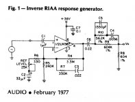
Instead of an opamp circuit a vintage solution might fit here.
(name is truncated by forum: "...application"; sourced from another topic somewhere here).
Tone control is included.
Attachments

Is this along the lines everyone advocating a TL072 opamp solution is discussing?
Haha! I can't type worth a damn today. I also wrote "Thank for very much for this response."
Thank you for another possible solution.
I'm curious to see. Thank you!
some men prefer silicones 🙂
Haha! I can't type worth a damn today. I also wrote "Thank for very much for this response."
MarsBravo said:Instead of an opamp circuit a vintage solution might fit here.
(name is truncated by forum: "...application"; sourced from another topic somewhere here).
Tone control is included.
Thank you for another possible solution.
wiseoldtech said:As an alternative to my previous post, a suitable, and simple network can be added to mate with an RIAA preamp, should the OP install a modern receiver with one.
I'll have to dig into my filing cabinet to find the schematic that I used for a "stand alone" 2G Microtouch changer that I sold last year.
The sound quality was amazing, and the buyer couldn't believe that it was the original ceramic.
I'm curious to see. Thank you!
Attachments
Last edited:
Attachments
Yes, silicon, sorry.
The 56k is "bootstrapped" to nearly 100 times higher.
Ceramics CAN be very-very good. Don't look/listen to the 99% which were all about price. One of their risks is poor aging especially in heat and humidity. By 1969 much of this problem was solved, at least in the sense that it shouldn't crap-out in the original owner's lifetime.
A ceramic does not inherently give the 6dB lift from 500Hz to 2kHz that RIAA prescribes. This can be done mechanically inside the cart, or externally in the preamp. I'm wondering where R111 leads off to.
I'm wondering where R111 leads off to.
Here's a full schematic of everything from the phono input all the way to the speakers. R111 leads to the other channel.
I'm also curious about the 2.2M resistor across the outputs for the cartridge.
Attachments
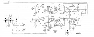
Here's a full schematic of everything from the phono input all the way to the speakers. R111 leads to the other channel.
I'm also curious about the 2.2M resistor across the outputs for the cartridge.
In some consoles, they used that arrangement to slightly "blend" the channels in order to reduce noise on stereo records and at the same time nullify any vertical rumble from the turntable.
It can be removed to increase seperation.
In some consoles, they used that arrangement to slightly "blend" the channels in order to reduce noise on stereo records and at the same time nullify any vertical rumble from the turntable.
It can be removed to increase seperation.
I figured it was to blend the channels, because that's obviously what it would do. But I saw several posts suggesting such an arrangement would somehow "tame the high end" and that puzzled me.
I figured it was to blend the channels, because that's obviously what it would do. But I saw several posts suggesting such an arrangement would somehow "tame the high end" and that puzzled me.
You'll get a ton of opinions about things like this.
When I read such things, I merely correct them, and usually get a bunch of flack.
I guess some people just don't like being called out for saying incorrect information.
- Home
- Source & Line
- Analogue Source
- High Impedance Input for a Vintage Turntable