Hello,
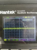
I have a problem with a really high frequency noise at the output of my Marantz M-CR603, a ~300kHz noise of ~1Vpp : (I precise the amp with loaded with an 8Ohm dummy load)
(see out_noise_1.jpg, and out_noise_2.jpg is the same noise but with a different temporal scale - we can see a slower other oscillations superposed on the other)
The amp features an SMPS power supply, and the amplification is digital, here the amplification scheme :
(see amplifier scheme.png)
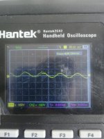
Now I have the feeling the noise is not normal. It is quite high in amplitude and I fear for my speaker, from what I have read on internet about high frequency noise and tweeter blowing. So I was looking for a culprit in the circuit. I first checked the power supply. There are two supply here, a +12V and a +32V. The +12V is not noisy at all. However, the +32V is really noisy (1Mhz noise). Here a picture of the rail with my scope AC coupled :
( see +32_noise.jpg)
I thought it may have been one of the SMPS capacitor (I already found some bad on it, that I've changed), so I've changed all of them with new one, but with no improvements.
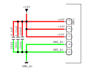
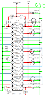
The supply comes from the SMPS board to the main board through CN61 (see filtering_1.png).
->Now on the schematics, I can see some small filtering cap at the entry on the board (see filtering_1.png), and some other at the digital amp chip (see filtering_2.png). The electrolytics are good (there are one per channel of 3300) and the little ones are film caps, nicely soldered.
So I guess all caps are good doing their job
-> Now, I see inductance in serie with the outputs, but both right and left channels of both A and B speaker output are noisy so I don't suspect a problem in a particular component bur rather in the supply.
-> So I am lost ! If supply is supposed to be good (but is it with a 1MHz noise ..?) and the signals paths are good, where is the problem coming from ? (but is there really a problem with the 1V, 300kHz noise at the speaker output ?)
Any ideas would be welcome !
Thanks
I have a problem with a really high frequency noise at the output of my Marantz M-CR603, a ~300kHz noise of ~1Vpp : (I precise the amp with loaded with an 8Ohm dummy load)
(see out_noise_1.jpg, and out_noise_2.jpg is the same noise but with a different temporal scale - we can see a slower other oscillations superposed on the other)
The amp features an SMPS power supply, and the amplification is digital, here the amplification scheme :
(see amplifier scheme.png)
Now I have the feeling the noise is not normal. It is quite high in amplitude and I fear for my speaker, from what I have read on internet about high frequency noise and tweeter blowing. So I was looking for a culprit in the circuit. I first checked the power supply. There are two supply here, a +12V and a +32V. The +12V is not noisy at all. However, the +32V is really noisy (1Mhz noise). Here a picture of the rail with my scope AC coupled :
( see +32_noise.jpg)
I thought it may have been one of the SMPS capacitor (I already found some bad on it, that I've changed), so I've changed all of them with new one, but with no improvements.
The supply comes from the SMPS board to the main board through CN61 (see filtering_1.png).
->Now on the schematics, I can see some small filtering cap at the entry on the board (see filtering_1.png), and some other at the digital amp chip (see filtering_2.png). The electrolytics are good (there are one per channel of 3300) and the little ones are film caps, nicely soldered.
So I guess all caps are good doing their job
-> Now, I see inductance in serie with the outputs, but both right and left channels of both A and B speaker output are noisy so I don't suspect a problem in a particular component bur rather in the supply.
-> So I am lost ! If supply is supposed to be good (but is it with a 1MHz noise ..?) and the signals paths are good, where is the problem coming from ? (but is there really a problem with the 1V, 300kHz noise at the speaker output ?)
Any ideas would be welcome !
Thanks
Attachments

Last edited:
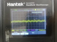
I've been measuring the input of the digital amplifier with no input in the amplifier. I got this at steady state :

So there is an input with the roughly the same frequency as my noise ! I am not well acquainted with digital amplifier, am I supposed to have this input from the PWM generator chip even with no signal ?
Also, with volume at 0, the noise disappears.
So there is an input with the roughly the same frequency as my noise ! I am not well acquainted with digital amplifier, am I supposed to have this input from the PWM generator chip even with no signal ?
Also, with volume at 0, the noise disappears.
I suspect there is no issue and what you are seeing is normal. SMPS and also Class D amps are both hotbeds of noise and hash production. 1v pk/pk at hundreds of kHz will not harm an inductive load like a speaker. Even into an 8 ohm resistive load, 1 volt pk/pk is just 16 milliwatts dissipation.

Hey Mooly ! Hope you're good.
Allright, that's what I've suspected so. Thing is it's hard to find doc about it on internet..
Thanks ! I'll try it so 🙂
Allright, that's what I've suspected so. Thing is it's hard to find doc about it on internet..
Thanks ! I'll try it so 🙂
If you measure the voltage across the speaker, not from one speaker lead to ground, you should measure much less noise.
And that is what the speaker sees, as explained by Mooly also.
BTW Class D is an analog amplifier, working with voltage, current and time, analog quantities.
A digital amplifier works with numbers.
Jan
And that is what the speaker sees, as explained by Mooly also.
BTW Class D is an analog amplifier, working with voltage, current and time, analog quantities.
A digital amplifier works with numbers.
Jan
Hey,
What do you mean by "across the speaker" ? Right now I am measuring between + and - of speaker output so I guess across the speaker ?
And here, I suspect we are really in a digital amp ! Analog inputs goes to a chip (AK4683) that features some ADC. Then, the chip communicates with an other (TAS5508B) who then emit some PWM signals for the final DAC chip (TAS5142)
It’s a little hard to read, but I think I saw 408kHz in one of the scope shots. That is almost certainly the modulation frequency of the Class D amplifier. It’s impossible to completely filter it out, so it’s normal to see some residual noise across a resistive load. The inductance of the speaker will filter out even more, so it’s inaudible and harmless to the speaker.
thanks for the input as well. Yes it is around the SMPS frequency🙂 I was just worried because I was reading some stuff on internet about high frequency noise killing tweeters, and I see no documentation about typical class D voltage level for the SMPS noise !
Yes you are already correctly measuring across the speaker, so nothing to gain there.Hey,
What do you mean by "across the speaker" ? Right now I am measuring between + and - of speaker output so I guess across the speaker ?
And here, I suspect we are really in a digital amp ! Analog inputs goes to a chip (AK4683) that features some ADC. Then, the chip communicates with an other (TAS5508B) who then emit some PWM signals for the final DAC chip (TAS5142)
Ideally, the high frequency signals at the class D switching frequency should have the same level and phase on each side of the speaker so the net HF signal across the speaker would be zero. But nothing in this world is ideal so there is always a residual, but it should be low and too high in frequency to bother the spaker.
And PWM signals are analog of course. It's all about voltage, current, time, all analog quantities.
A digital amp would be something where you input a number and the output is a number.
Like input is 1011 and output is 10110 for a gain of two.
Not a matter of life and death but we should avoid confusion when possible.
Jan
We’re down to splitting words here, but the TAS5142 is the amplifier and takes a PWM signal that’s technically analog. The TAS5508B is an audio processor that accepts a wide range of inputs and puts out PWM. The PWM inside that chip is almost certainly analog, since building a digital PWM would require extreme clock frequencies.Hey,
What do you mean by "across the speaker" ? Right now I am measuring between + and - of speaker output so I guess across the speaker ?
And here, I suspect we are really in a digital amp ! Analog inputs goes to a chip (AK4683) that features some ADC. Then, the chip communicates with an other (TAS5508B) who then emit some PWM signals for the final DAC chip (TAS5142)
Oh okay I see what you mean. Totally agree, a number is not taller than any other by itself..
I was just saying that the amp didn't seem like a pure class D to me with the analog signal directly driving the modulation, but through a first ADC. I was reading this article this morning about it that I've found interesting :https://www.audioholics.com/audio-amplifier/the-truth-about-digital-class-d-amplifiers
I was just saying that the amp didn't seem like a pure class D to me with the analog signal directly driving the modulation, but through a first ADC. I was reading this article this morning about it that I've found interesting :https://www.audioholics.com/audio-amplifier/the-truth-about-digital-class-d-amplifiers
Are you sure it is the SMPS noise? SMPS switching frequency is generally much lower, even lower than 100kHz. 400kHz sounds more like the class D amp frequency.thanks for the input as well. Yes it is around the SMPS frequency🙂 I was just worried because I was reading some stuff on internet about high frequency noise killing tweeters, and I see no documentation about typical class D voltage level for the SMPS noise !
Jan
Are you sure it is the SMPS noise? SMPS switching frequency is generally much lower, even lower than 100kHz. 400kHz sounds more like the class D amp frequency.
Hum you're right, the datasheet of the clocking shows a 67kHz switching frequency..
We’re down to splitting words here, but the TAS5142 is the amplifier and takes a PWM signal that’s technically analog. The TAS5508B is an audio processor that accepts a wide range of inputs and puts out PWM. The PWM inside that chip is almost certainly analog, since building a digital PWM would require extreme clock frequencies.
I will try to read more about this, my mind is not fully following the signal path I think !
Digital PWMs are infeasible due to the math. CD quality has 44100 samples/s, so each sample is about 23us in duration. If you want 16 bits amplitude resolution, it means that you need to vary the pulse with in steps 23e-6/65536=3.51×10⁻¹⁰ seconds. This means that you need a clock running at 1/3.51e-10=2.8GHz. While that’s achievable, it’s expensive and creates a whole slew of new problems that only get worse when you’re starring to get into 24 bits and 192kHz sampling frequency. You could build the whole thing as a sigma/delta DAC with some powerful FETs at the output. I’ve actually tried that for fun with an FPGA, and it works. But as far as I know, it’s not widely used.I will try to read more about this, my mind is not fully following the signal path I think !
Caveat: I haven’t been following the Class D state of the art that closely lately, so there might be some “predominantly digital” designs out there these days. But last time I checked, people still agreed with Bruno that digital designs didn’t offer anything above and beyond good old analog PWMs.
- Home
- Amplifiers
- Solid State
- High frequency output noise - Marantz M-CR603