I recently built a stereo LM3886 amplifier following the guide on Circuit Basics - Arduino, Raspberry Pi, and DIY Electronics Tutorials. Except for the fact that I made my own PCBs, I followed the guide religiously, including the ground loop protection circuit.
https://www.circuitbasics.com/design-hi-fi-audio-amplifier-lm3886/
I designed the PCBs and had them fabricated before assembling the boards, only to hear a very distinct and constant ~6.3kHz and ~13kHz noise on the output. Immediately on startup, it isn't present, but then within ~3 seconds it's there and remains constant. The noise is not affected by any input signal, or whether or not the RCA cables are connected.
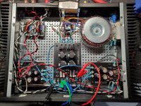
Attached is a picture of the amp after discovering that even with the clean benchtop power supply (transformer and power supply board disconnected), I still get the noise.
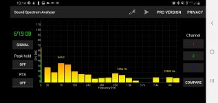
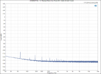
Also attached is a screenshot of as free spectrum analyzer app showing the noise (7.4k and 14k) with no signal going into the amp.
I've been searching diyaudio.com/google for other people with LM3886 noise issues, and it seems like they are all related to ground loops. If anyone has any suggestions, please let me know!
Thank you!
https://www.circuitbasics.com/design-hi-fi-audio-amplifier-lm3886/
I designed the PCBs and had them fabricated before assembling the boards, only to hear a very distinct and constant ~6.3kHz and ~13kHz noise on the output. Immediately on startup, it isn't present, but then within ~3 seconds it's there and remains constant. The noise is not affected by any input signal, or whether or not the RCA cables are connected.
- I have played around with grounding layouts - no change
- I've added different EMI filters on the mains voltage - no change
- I've plugged it into different locations in my house (get away from fluorescent lights, etc) - no change
- I've swapped out the power supply for a high-end benchtop power supply - no change
- At one point, the V+ for the left channel was loose, and wiggling it around caused the noise to temporarily cease. Making sure every connection is tight has resulted in no change.
Attached is a picture of the amp after discovering that even with the clean benchtop power supply (transformer and power supply board disconnected), I still get the noise.
Also attached is a screenshot of as free spectrum analyzer app showing the noise (7.4k and 14k) with no signal going into the amp.
I've been searching diyaudio.com/google for other people with LM3886 noise issues, and it seems like they are all related to ground loops. If anyone has any suggestions, please let me know!
Thank you!
Attachments
It must be oscillating, are you sure all the parts are right?
The input and output wiring do appear to be long and close together.
Try moving both of the white/black pairs away from both of the red/black pairs.
If you are open to rebuilding, it would be better to locate each channel's pcb, associated
sockets, and wiring near its own heat sink, with the toroid and power supply in the middle.
The input and output wiring would be much shorter and more direct this way.
Last edited:
Has your circuit got a Zobel network connected from the chip output pin to ground?
You could also carefully try a very small value cap across the feedback resistor. Assuming the resistor is around 22k then try a 18 or 22pF cap.
You could also carefully try a very small value cap across the feedback resistor. Assuming the resistor is around 22k then try a 18 or 22pF cap.

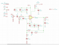


That looks a fairly standard circuit that should perform OK.
The frequencies you hear are a bit low to be normal HF oscillation unless they are artefacts of a much higher frequency.
Its very hard to say tbh. You must make sure the grounding is correct.
If it isn't already then try returning the speaker negative back to the power supply ground directly and not the amp boards... hard to follow from pictures 🙂
Can you describe the "High frequency noise"? Do you hear the sound in the speaker? Both channels? Still present when only one board is powered?
I am not criticizing your board, but those decoupling caps are super far from the chip legs, c7/c5 are suppose to be ceramic or film capacitors, usually next to the chip. C2/C9 are missing ? I cannot see the ground plane , maybe a picture of the actual board would be better. Or gerber files.
I am not criticizing your board, but those decoupling caps are super far from the chip legs, c7/c5 are suppose to be ceramic or film capacitors, usually next to the chip. C2/C9 are missing ? I cannot see the ground plane , maybe a picture of the actual board would be better. Or gerber files.
Ground loops and loop area are the cause of the noise. Input grounds should not be connected to the power board. Use interconnect cable for the inputs. Twist the ac wires before and after the transformer. For best results, place the amp boards close together.
Also, use ground loop breaker (GLB) and hum breaking resistors (HBR).
Others have had the same problems using that design.
Others have had the same problems using that design.
Last edited:
You should connect the chassis to mains earth which you have done, but connect this to the circuit through a 10r resistor, not directly as it seems from your photo.
You should use 'star' earthing with speaker returns going to it and not the pcb.
Use screened cable for the input leads, and insulated input sockets.
You should use 'star' earthing with speaker returns going to it and not the pcb.
Use screened cable for the input leads, and insulated input sockets.
Last edited:
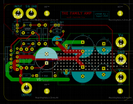
Your issue is most likely not due to a ground loop. More than likely it is due to the placement of the decoupling capacitors. You need a low-impedance path from the decoupling networks to the IC. Low impedance = short, wide trace (or pour). Have a look at this layout for example: An open source layout for LM3886?
The purpose of the decoupling network is to make the IC "see" a low impedance at all frequencies, especially at the frequencies where it tends to oscillate. When you place the decoupling network far away from the IC, you introduce a sizeable inductance in series with the decoupling network. This increases the power supply impedance "seen" by the IC.
To address this in your circuit, de-solder the 22 uF and the 4.7 uF capacitors from the PCB and solder them directly from the IC pins to ground. I would do this on the bottom of the board. If you used a ground plane, you can scrape the solder mask off in a spot to get a grounding point for the decoupling network. I bet moving the decoupling network will solve your issue. If it does, you can then decide whether you want to redo the board or just leave it as-is.
You can read more about power supply decoupling here: Taming the LM3886 Chip Amplifier: Power Supply Decoupling – Neurochrome
That's a violation of the electrical code in most countries. The mains earth must go directly to the chassis.
That's a great way to introduce distortion - and not a pleasantly sounding one. You can see my measured data here: LM3886 PCB vs Point-to-Point (with data)
I suggest grounding the SIGGND at the negative speaker terminal. In fact, you can probably just take the ground from the power supply, the GND from the PCB, and the SIGGND from the PCB to the negative speaker terminal and call it good. I personally prefer to make that connection on the PCB, but that's not to say that that's the only way to do things. I've attached a measurement of the residual mains hum in my LM3886DR for reference.
For the full explanation, see here: Taming the LM3886 Chip Amplifier: Grounding – Neurochrome
I agree. The Neutrik NF2D connectors are excellent for this ... and really quite affordable.
Tom
The purpose of the decoupling network is to make the IC "see" a low impedance at all frequencies, especially at the frequencies where it tends to oscillate. When you place the decoupling network far away from the IC, you introduce a sizeable inductance in series with the decoupling network. This increases the power supply impedance "seen" by the IC.
To address this in your circuit, de-solder the 22 uF and the 4.7 uF capacitors from the PCB and solder them directly from the IC pins to ground. I would do this on the bottom of the board. If you used a ground plane, you can scrape the solder mask off in a spot to get a grounding point for the decoupling network. I bet moving the decoupling network will solve your issue. If it does, you can then decide whether you want to redo the board or just leave it as-is.
You can read more about power supply decoupling here: Taming the LM3886 Chip Amplifier: Power Supply Decoupling – Neurochrome
You should connect the chassis to mains earth which you have done, but connect this to the circuit through a 10r resistor, not directly as it seems from your photo.
That's a violation of the electrical code in most countries. The mains earth must go directly to the chassis.
You should use 'star' earthing with speaker returns going to it and not the pcb.
That's a great way to introduce distortion - and not a pleasantly sounding one. You can see my measured data here: LM3886 PCB vs Point-to-Point (with data)
I suggest grounding the SIGGND at the negative speaker terminal. In fact, you can probably just take the ground from the power supply, the GND from the PCB, and the SIGGND from the PCB to the negative speaker terminal and call it good. I personally prefer to make that connection on the PCB, but that's not to say that that's the only way to do things. I've attached a measurement of the residual mains hum in my LM3886DR for reference.
For the full explanation, see here: Taming the LM3886 Chip Amplifier: Grounding – Neurochrome
Use screened cable for the input leads, and insulated input sockets.
I agree. The Neutrik NF2D connectors are excellent for this ... and really quite affordable.
Tom
Attachments
Last edited:
RE mains earthing
You misread my post. I stated that the mains earth does indeed have to connecs to the chassis, but 10r is a ground loop breaker connecting mains earth (chassis) to the amps 0v.
You misread my post. I stated that the mains earth does indeed have to connecs to the chassis, but 10r is a ground loop breaker connecting mains earth (chassis) to the amps 0v.
Update
Everyone has some great feedback, definitely thinking of pcb redesign, as well as abandoning the m4 SHCS interconnects- troubleshooting has taken forever as a result of having to screw and unscrew them constantly.
Here is the update: if I only have one lm3886 board plugged in, the thing sounds great. No hum, clean as one could hope. Left or right, they sound the same. However, if I try to connect both channels at the same time, I get the noise. All I'm doing is connecting or disconnecting the v+ and v-. Im not disconnecting speakers, rca inputs, or grounds.
Does this support the decoupling caps from being too far away? Does there need to be more isolation between input signal grounds?
Thoughts?
I would agree that the decoupling is too far away. But that's not the likely culprit.
The fact that the noise only happens when both are connected points to a ground loop.
In the schematic, I can't see a connection between SIGGND and GND nodes. How are they actually connected to each other?
Edit: Oh I see it now.
That is the wrong way to hook up an input and ground, You want the inputs to go directly to the PCB, not route the SGND through the power supply board.
The SGND and GND nodes can be directly connected under the PCB. the negative node on the 470uF can be hooked up to the speaker output GND (not the cleanest, but will be better than what you have now.
Here is the update: if I only have one lm3886 board plugged in, the thing sounds great. No hum, clean as one could hope. Left or right, they sound the same. However, if I try to connect both channels at the same time, I get the noise.
That points to a ground loop and/or poor ground management. Are your input connectors isolated from the chassis?
Another thing to try would be to leave both channels connected but unplug one RCA cable on the input.
Does this support the decoupling caps from being too far away?
No. But I would still move the decoupling caps. I've seen the LM3886 oscillate with poor decoupling, especially at high output current. Oscillations will kill your tweeters.
Tom
My theory is the source of the interference is probably something like a cheap LED light fitting with a brightness control, which uses PWM at audio frequencies. This injects into the mains, it sails into the amp (normal mains filters don't work down to audio freqs).
One test is plug it in in another room, or building even, see if the noise goes?
One test is plug it in in another room, or building even, see if the noise goes?
- Home
- Amplifiers
- Chip Amps
- High frequency noise with DIY LM3886 build - Help