I have always wondered about the propriety of using the wrong regulator (338 for negative rails and 138 for positive rails).
Any thoughts on this?
Any thoughts on this?
Do you mean :
voltage of (X-Y) = -25.7?
voltage of (A-B) = +26.2?
Yes I do (and I checked it again to make sure I am not going mad!
How do you put your C2's polarity
Positive side to adjust - like the other three!
My guess is that he has one of the center-tap wires reversed with a outer tap wire. Or perhaps he has the center taps going to the wrong side of the circuit.
GWB - I think that it must be some intereraction with the positive side of the circuit but I cannot see what is wrong.
A curious set of readings, to be sure! Have you measured from A to X on your schematic? When functioning properly the LM338 should be giving 1.24 +/- .05 V between output and adjust.
I'm getting 0.6 volts Saabie! 😕 😕 😕
Nick, if you disconnect that reg's output from the ground (A), what do you get?
Answer: -26.2 volts Pedja! 😱 (Do I win a regulated PSU? 😀 )
Carlos, could I ask you to stand by for the next three hours in case I need your help? Please turn off your TV and wait by the PC. 🙄 
Nuuk, are you sure that the secondaries are actually separate? This might be the source of your problems.
Cheers
Andrea
Cheers
Andrea
Nuuk said:Carlos, could I ask you to stand by for the next three hours in case I need your help? Please turn off your TV and wait by the PC. 🙄
Gotta make a break, as you understand.
I hope this time is a 90 minute break.😀
Nuuk, those caps on the Adj pin should have the + side to Adj.
The reading you have between A and B should be negative!😕
Check the PSU diodes / bridges, are you sure it's all correct?
Didn't reverse anything?
Sometimes things blow up only when you demand current, as connecting your amp.
Note: stand back before power on, I'm not joking, if something's wrong you can hurt yourself.
Oh, kisses for your gf.🙂
Nuuk, are you sure that the secondaries are actually separate? This might be the source of your problems.
Quite sure Andrea! 😉
Both regulator modules are fed from the same transformer and rectifier bridges. One channel works OK on this supply.
Nuuk, those caps on the Adj pin should have the + side to Adj.
Carlos, the caps have their positive side to adjust.
The reading you have between A and B should be negative!
I wish it was! 🙁
Check the PSU diodes / bridges, are you sure it's all correct?
Didn't reverse anything?
Transformer/rectifier section is fine (see above).
Sometimes things blow up only when you demand current, as connecting your amp.
Yes, but I have not connected anything other than a meter.
Note: stand back before power on, I'm not joking, if something's wrong you can hurt yourself.
I will (and even more so after power on 😉 )
We win!!!
Thanks matjans.
But... is it always the ref?🙄
We scored 3 goals and win 2-1.
😎
matjans said:tsk, that referee didn't do a really good job now, did he? 😡 😱
congrats, carlos.
Thanks matjans.
But... is it always the ref?🙄
We scored 3 goals and win 2-1.
😎
Welcome to the club Matjan 😉 It's written in the sands that the homeside will win this tournament (and the referees have been playing on the beach)
Did you wonder why Collina will not be refereeing the final?
Did you wonder why Collina will not be refereeing the final?
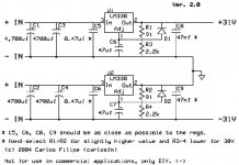
Revision
I'm making some tests...
I was not using exactly the values of the resistors I posted on my schematic, because I was using a trim pot in R3/R4.
The trimpot is not a very good idea, as it drifts, and voltage gets a little lower after some hours, I changed them for resistors.
Or they are good or don't bother.
Just use resistors, is what I recommend.
In these tests I'm finding that the value of R1/R2 is important.
The lower the better.
This gives more continuous current and a heavier load on the trafo, but the benefit is a lower output impedance, even at idle (very low volume).
I post the revised schematic, with lower resistor values.
I selected standard values, having in mind that I wanted R1/R2 around 100 ohms or a little below.
If you want 30 volts, using 5% resistors, measure them, as explained in the schematic.
Here it is, forgive me, but there's nothing interesting on TV (except football😀 ), and I keep tweaking this.🙂
Attachments
Nuuk said:Welcome to the club Matjan 😉 It's written in the sands that the homeside will win this tournament (and the referees have been playing on the beach)
Did you wonder why Collina will not be refereeing the final?
Calm down guys, we scored 3 goals, we were your friends.😀
Take the ref out of this.
It just hit me in the head...
That it's probably better to use a single pair of regs for both chips, as I use.
It's enough IMHO, and demanding more current to the regs lowers the PSU impedance.
Just use good heatsinks.
That it's probably better to use a single pair of regs for both chips, as I use.
It's enough IMHO, and demanding more current to the regs lowers the PSU impedance.
Just use good heatsinks.
carlosfm said:
Calm down guys, we scored 3 goals, we were your friends.😀
Take the ref out of this.
The referee Frysk wasn't as good as required but we should not complain about that as it could have been worse.
Although Portugal deserved to win the game I found their actorship when a ball or a dutch player was in proximity rather annoying. Couldn't they just play and win instead of falling to the ground every 5 minutes just to win time ? The only players that really did well were Ronaldo and Figo IMO.
That it's probably better to use a single pair of regs for both chips, as I use.
Well, I would like to get my second channel working but I may have to take your suggestion Carlos. Although, that will mean a complete change in my amplifier layout! 🙁
jean-paul said:Although Portugal deserved to win the game I found their actorship when a ball or a dutch player was in proximity rather annoying. Couldn't they just play and win instead of falling to the ground every 5 minutes just to win time ? The only players that really did well were Ronaldo and Figo IMO.
J-P, it's always annoying when a team takes the lead and tries to loose time in their advantage.
England did that for some 80 minutes against us.
It didn't work.😀
It probably does but only marginally, since in this case this impedance is hugely defined by the feedback. Note that here this lower impedance might not be necessarily positive thing.carlosfm said:That it's probably better to use a single pair of regs for both chips, as I use.
It's enough IMHO, and demanding more current to the regs lowers the PSU impedance.
Well I just had to try taking the regulator circuit out of my amp, I replaced the smaller caps on the LM3875 pins with 1000uf and let it run in for a couple of hours.
So now I have normal GC but with buffer,
first impressions are everything sounds thin, the bass now sounds loose but worst of all those beautiful mids are gone.
The amp is back to normal and is making music again, sorry I just had to make sure
So now I have normal GC but with buffer,
first impressions are
everything sounds thin, the bass now sounds loose but worst of all those beautiful mids are gone.The amp is back to normal and is making music again, sorry I just had to make sure
Nuuk, let's see if we find out what's happening with your regs...
You have 8 diodes (2 bridges) and 2 pairs of regs, right?
That is, the two pairs of regs share the same diodes, right?
Now look at the schematic.
You join the output of one reg with the ground of the other one to make the ground, right?
What happens if on the other board you pick the other two lines to do this?
- Status
- Not open for further replies.
- Home
- Amplifiers
- Chip Amps
- High-End Regulated Buffered Inverted GC