The problem with AIC is that it is another coil that needs to be powered and creates more heat. Not the direction you want to go. It is also fixed in the gap so as the coil moves above and below the gap, inductance still changes.
http://www.eighteensound.com/staticContent/technologies/products/aic.pdf
Their own paper proves that a shorting ring is a better option. Look at figure 49 on page 17 for example. By shorting the AIC coil you get the largest drop in inductance. As you are shorting that coil, all you are doing is making it a solid copper ring. A full sleeve over the entire pole is even more effective at linearizing Le than any of the options they sho.
John
gedlee said:
Further, USPS is the best deal in shipping anywhere. It can't be beat if they will take what you want to ship. But they do have size and weight limits.
I'd just like to jump on this bandwagon. USPS is a fantastic organization. When you ship that many packages, there are bound to be some problems, but I ship USPS nearly exclusively, and have had no issues. Most post employees are courteous and professional, too, naturally with some exceptions.
Not really, judging from the graphs of drivers with shorting rings. I think the only drivers that display this behavior are the ones using a full copper sleeve.gedlee said:Thats what a short ring of alluminum does. A "coil" of multiple turns would not be as effective as a single turn of large cross section.
Not a significant concern as some of their AIC drivers are the most efficient I ever seen (in fact, more efficient with the AIC connected). Power compression alleged by the manufacturer remains low.John_E_Janowitz said:The problem with AIC is that it is another coil that needs to be powered and creates more heat. Not the direction you want to go.
Also, you read the graph wrong. Wiring it in parallel achieves the biggest drop in inductance.
tech.knockout said:Not really, judging from the graphs of drivers with shorting rings. I think the only drivers that display this behavior are the ones using a full copper sleeve.
It's true that a ring at the base of the magnet will not affect the inductance while one that is close to the voice coil will. My answer was simplistic since I didn't see the need to get into this kind of detail. I agree with John that this AIC idea does not seem to be very effective. What John does in his speakers is pretty much the ideal (maybe a little more ideal than really necessary).
Well, of the drivers with shorting rings; you have to look very hard to find one with such a flat impedance curve, even the ones with a copper cap (which i presume is near the coil).gedlee said:
It's true that a ring at the base of the magnet will not affect the inductance while one that is close to the voice coil will. My answer was simplistic since I didn't see the need to get into this kind of detail. I agree with John that this AIC idea does not seem to be very effective. What John does in his speakers is pretty much the ideal (maybe a little more ideal than really necessary).
The only commercial drivers I know that has this is the JBL high output midrange series and that has a full copper sleeve like the lambdas. And even then they aren't as efficient, im guessing the copper sleeve saps the motor strength.
It certainly isnt a revolution over a big sleeve/ring; but my point was that its a good way to set yourself apart from the rest.
The copper sleeve need not cost any motor strength. Statically the copper does nothing. It takes up some gap space, but this can be compensated for by the magnet structure design.
I can only see the *need* for reducing the inductance in a midrange or tweeter. I really don't see any need for it in a woofer. But woofers DO need flux modulation control, especially if they carry a large bandwidth. Its the change in inductance and flux with current that is the issue not the actual inductance itself (in a woofer).
I can only see the *need* for reducing the inductance in a midrange or tweeter. I really don't see any need for it in a woofer. But woofers DO need flux modulation control, especially if they carry a large bandwidth. Its the change in inductance and flux with current that is the issue not the actual inductance itself (in a woofer).
In our drivers we take off .025" of steel all the way around the pole, then put the copper sleeve on in place. That means you do have a reduction in BL vs no copper on the pole. It's not the copper causing the drop in BL it's just the steel being removed. Then you can always go with a larger motor to get the Bl back to the point where it is needed. It does increase cost a little but it's worth the efforts.
We do the copper for several reasons. Lowering inductance in a driver used only to 80hz or so isn't as critical as in a high bandwidth driver, but it is still important. If you look at some of the drivers that TC was doing for us back 5 yrs ago, they had such high inductance that there was a big hump centered between 45-70hz, depending on which model. Then it rolled off quickly above there. This hump can be EQ'd out but distortion skyrockets there and it makes your phase do goofy things. I like to have a drive with relatively flat electrical response at least to the Xover point if not for an octave or more past there. It makes crossover integration much more simple.
This was a curve measured by Tom Nousaine several years back on the enclosure with the HE15 and PR's. You can see the bump in the response centered at 70hz. This was about a 6ohm driver coils in parallel with 10mH inductance.
You can see that the measured results are quite close to what is predicted in the simulations in terms of response. The other big issue seen is with the group delay in that range.
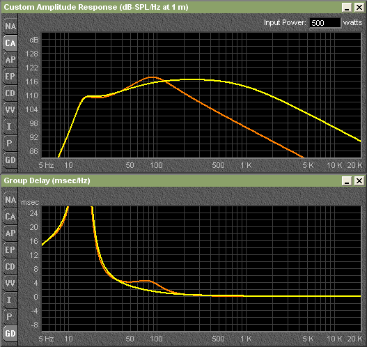
The yellow curves are what the effect would be with sleeving the pole with an appropriate copper sleeve and the same Bl.
John
We do the copper for several reasons. Lowering inductance in a driver used only to 80hz or so isn't as critical as in a high bandwidth driver, but it is still important. If you look at some of the drivers that TC was doing for us back 5 yrs ago, they had such high inductance that there was a big hump centered between 45-70hz, depending on which model. Then it rolled off quickly above there. This hump can be EQ'd out but distortion skyrockets there and it makes your phase do goofy things. I like to have a drive with relatively flat electrical response at least to the Xover point if not for an octave or more past there. It makes crossover integration much more simple.
This was a curve measured by Tom Nousaine several years back on the enclosure with the HE15 and PR's. You can see the bump in the response centered at 70hz. This was about a 6ohm driver coils in parallel with 10mH inductance.
You can see that the measured results are quite close to what is predicted in the simulations in terms of response. The other big issue seen is with the group delay in that range.
The yellow curves are what the effect would be with sleeving the pole with an appropriate copper sleeve and the same Bl.
John
John
I don't worry about group delay at those frequencies, but 10 mH inductance is excessive. The B&C woofer is 1.6 mH which does not end up being a problem even up to 1 kHz. They use a shorting ring rather than a copper cap so there is not much inductance lowering from it.
I don't worry about group delay at those frequencies, but 10 mH inductance is excessive. The B&C woofer is 1.6 mH which does not end up being a problem even up to 1 kHz. They use a shorting ring rather than a copper cap so there is not much inductance lowering from it.
gedlee said:I don't worry about group delay at those frequencies
I find this a little odd. While I don't think it's as troublesome as delay at higher frequencies, it's definitely audible.. to me, anyway. Speaking of which, I've been experimenting lately with using lower 2nd order lowpass crossovers on subwoofers instead of the common 4th order placed an octave higher. The results I've obtained from trying this are very good so far. Has anyone else done this?
BHTX said:it's definitely audible.. to me, anyway.
I think that it needs to be audible to people in general under blind conditions using real world signals. All tests that I know of like this have found this to not be the case.
A different perspective
Instead of promoting eddy currents in shorting rings to reduce Le, ATC goes the opposite direction--minimizing eddy currents and increasing Le by lining the magnetic gap with a magnetic material that features resistivity (they call it SLMM).
Here's an excerpt from ATC's company profile and technical philosophy paper.
I haven't taken the time to run simulations to confirm this, but I find the idea facinating. Any comments?
Instead of promoting eddy currents in shorting rings to reduce Le, ATC goes the opposite direction--minimizing eddy currents and increasing Le by lining the magnetic gap with a magnetic material that features resistivity (they call it SLMM).
Here's an excerpt from ATC's company profile and technical philosophy paper.
The third source of distortion is due principally to the inherently non-linear magnetic performance of steel. The alternating magnetic field created by the voice coil induces eddy currents into both the pole and front plate, adjacent to the coil, of the permanent magnet assembly. These eddy currents flow in such a way as to oppose the magnetic field producing them, (i.e. from the voice coil), and cancel out much of the self inductance. This mechanism is minimized in ATC bass and bass/mid drive units by the use of a new material, which has the unique properties of high magnetic permeability and saturation as well as low electrical conductivity.We call it a super linear magnet material (SLMM). With this material fitted to the pole and front plate adjacent to the voice coil the eddy currents are suppressed and the impedance (self inductance) increases. The result is that third harmonic distortion is reduced by between 12–15dB.
I haven't taken the time to run simulations to confirm this, but I find the idea facinating. Any comments?
In another document that doesn't seem to be on ATC's website anymore, they go into more particulars:
Experiments were performed on a blocked voice coil with the magnet left un-energised. It could be thought of as a cored inductor. A current was passed through the coil and second and third harmonic distortion components were measured. Mathematical analysis, in conjunction with the experiments, has revealed some surprising answers to the question of why replacing the steel regions with S.L.M.M. has such a dramatic effect on the distortion.
(Snip)
...the presence of the S.L.M.M. increases the self-inductance of the voice coil. When eddy currents are allowed to circulate in the system, they oppose the magnetic field producing them (i.e. that from the coil) and ‘cancel out’ much of the self-inductance. With the S.L.M.M. in place, eddy currents are suppressed and the self-inductance (i.e. the impedance) goes up. thirdly, whilst the impedance, and therefore the fundamental voltage across a blocked coil goes up when the rings are fitted, the harmonic components, that are induced back into the voice coil, stay the same. This is because they are dependent only on magnetic field, which as we have seen, doesn’t change very much. The net effect is a rise in the signal/distortion ratio.
- Status
- This old topic is closed. If you want to reopen this topic, contact a moderator using the "Report Post" button.
- Home
- Loudspeakers
- Multi-Way
- High efficiency 15"