You know, theres a power supply section on this board. I posted some basic walk-throughs on stacking ~90A server power supplies connected to 220v dedicated circuits, supplies modified to output 14.5vDC. I've had this setup supply 500A briefly (Pegged my cheap 500A shunt monitor).
Did you see it?
https://www.diyaudio.com/community/...stna-pd18-power-supplies.375967/#post-6771510
Did you see it?
https://www.diyaudio.com/community/...stna-pd18-power-supplies.375967/#post-6771510
Last edited:
Some updates.
This quickly went from a budget build to a 'do it right' build, to a... Wish I had just bought a proper high power supply build.
Anyway, here we are.. enjoy tinkering anyway so it's whatever, but spent considerably more than anticipated on misc parts.
Regarding the high temperature in the ucc37323 chip, the first unit I had actually has issues there. Not entirely sure why, but I did A LOT of messing around on that supply initially. Hoping the chip is faulty, I have some on order. Pic of good vs bad output below.

That chip does run hotter than normal with the new higher voltage, but it's considerably hotter on this unit. I'm adding small copper heatsinks to each chip on all three supplies, but hope to get supply #1 running normally first obviously.
Will be using a 30A industrial type light switch to switch main power off at the input once built. Will be adding a 100k/led/1n4007 indicator led there to remind me it's on.
https://www.menards.com/main/electr...1-c-6324.htm?tid=-1260490037570863734&ipos=33
12awg wiring to wall (220v/20A at wall) which will be spliced to these cables to the supplies. Originally bought some garbage c13 screw apart headers on eBay that are yeah garbage..
https://smile.amazon.com/gp/aw/d/B08W9GMQ6Y?psc=1&ref=ppx_pop_mob_b_asin_image
Will wire an on/off switch to enable supplies output too. Pin33 on each supply will go to a Schottky to switch which will ground them out and turn on.
300A shunt for current monitoring with display, and 4 digit voltage monitoring will be built into supply.
https://www.ebay.com/itm/182775199175
https://smile.amazon.com/gp/aw/d/B07DFQ9LJQ?psc=1&ref=ppx_pop_mob_b_asin_title
With the extra heat on the switcher chip, I wanted a better way to control the fan speeds on these. Wanted them higher a bit by default and not just full speed once at a certain threshold (which is how this supply works, tried playing with multiple ntcs in the units).
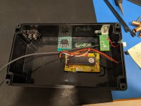
Decided to buy one of these temp controlled pwm controllers and tested it out. Works great! Programming it is kind of a pain but nice once done. Can set base speed for fan, a temp point which speed begins increasing, and a temp point for max speed. I'll have the probe in only one unit, but pwm controller used on all fans. Fan supplies will be left coming from units, and tach pin left in place (required).
https://www.ebay.com/itm/382653081487
I also am wiring a pot in parallel with the ntc on the controller (with its own series R to set minimum resistance of course), so I can have manual control.
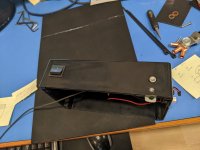
What else.. 250A breaker on output will be installed. Project box for all the meters etc of course.
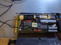
4awg ofc wiring, went back and forth on that but my main connection out will only be a couple feet long at most. 8awg 4-6" positive wiring from each supply to breaker where they'll join up to help with current sharing.
Status indicator leds and wiring in each supply will be routed out to the project box for easy viewing.
Suppose it's a bit more interesting with pictures.... Soon 🙂.
This quickly went from a budget build to a 'do it right' build, to a... Wish I had just bought a proper high power supply build.
Anyway, here we are.. enjoy tinkering anyway so it's whatever, but spent considerably more than anticipated on misc parts.
Regarding the high temperature in the ucc37323 chip, the first unit I had actually has issues there. Not entirely sure why, but I did A LOT of messing around on that supply initially. Hoping the chip is faulty, I have some on order. Pic of good vs bad output below.
That chip does run hotter than normal with the new higher voltage, but it's considerably hotter on this unit. I'm adding small copper heatsinks to each chip on all three supplies, but hope to get supply #1 running normally first obviously.
Will be using a 30A industrial type light switch to switch main power off at the input once built. Will be adding a 100k/led/1n4007 indicator led there to remind me it's on.
https://www.menards.com/main/electr...1-c-6324.htm?tid=-1260490037570863734&ipos=33
12awg wiring to wall (220v/20A at wall) which will be spliced to these cables to the supplies. Originally bought some garbage c13 screw apart headers on eBay that are yeah garbage..
https://smile.amazon.com/gp/aw/d/B08W9GMQ6Y?psc=1&ref=ppx_pop_mob_b_asin_image
Will wire an on/off switch to enable supplies output too. Pin33 on each supply will go to a Schottky to switch which will ground them out and turn on.
300A shunt for current monitoring with display, and 4 digit voltage monitoring will be built into supply.
https://www.ebay.com/itm/182775199175
https://smile.amazon.com/gp/aw/d/B07DFQ9LJQ?psc=1&ref=ppx_pop_mob_b_asin_title
With the extra heat on the switcher chip, I wanted a better way to control the fan speeds on these. Wanted them higher a bit by default and not just full speed once at a certain threshold (which is how this supply works, tried playing with multiple ntcs in the units).
Decided to buy one of these temp controlled pwm controllers and tested it out. Works great! Programming it is kind of a pain but nice once done. Can set base speed for fan, a temp point which speed begins increasing, and a temp point for max speed. I'll have the probe in only one unit, but pwm controller used on all fans. Fan supplies will be left coming from units, and tach pin left in place (required).
https://www.ebay.com/itm/382653081487
I also am wiring a pot in parallel with the ntc on the controller (with its own series R to set minimum resistance of course), so I can have manual control.
What else.. 250A breaker on output will be installed. Project box for all the meters etc of course.
4awg ofc wiring, went back and forth on that but my main connection out will only be a couple feet long at most. 8awg 4-6" positive wiring from each supply to breaker where they'll join up to help with current sharing.
Status indicator leds and wiring in each supply will be routed out to the project box for easy viewing.
Suppose it's a bit more interesting with pictures.... Soon 🙂.
Last edited:
Ucc37324... not 37323. That was an exciting flame effect... good chance this one is done for.
Smh.
Smh.
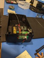
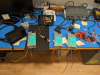
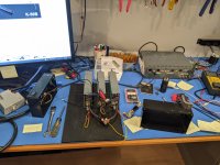
Input side to the chip is nearly/shorted to gnd. Junk pile for that one. I'll get a different of same rev (2F fyi). Some random pics of progress..


Guess the current meter I bought requires a fully isolated supply, neato..... don't buy that one.
Grabbed PESE1-S12-S9-M-TR from digikey.
https://www.mouser.com/datasheet/2/670/pese1_m-1596013.pdf
Grabbed PESE1-S12-S9-M-TR from digikey.
https://www.mouser.com/datasheet/2/670/pese1_m-1596013.pdf
Seemed like the proper thing to do, in a scenario of a dead short somehow.What's the reason for the 250 amp breaker?
Think it would be better to forget the breaker?
The supplies should have over-current protection. The breaker could be used to protect the wiring but having large enough wire to take the full current would eliminate the need for the breaker.
Breakers aren't very good for protecting the amp. A solenoid driven by a comparator would be a better solution if you want to protect an amplifier. The comparator would monitor the voltage across the shunt and switch the solenoid off when a preset value is reached.
Breakers aren't very good for protecting the amp. A solenoid driven by a comparator would be a better solution if you want to protect an amplifier. The comparator would monitor the voltage across the shunt and switch the solenoid off when a preset value is reached.
Ok I'll mull that over a bit.
Earth ground is tied to DC out ground in these.
Any reason I should Considering floating the output ground from earth ground? Would leave earth gnd in tact in chassis and input side.
Started thinking that over, but don't know of any real reason to go there... I'm obviously not running these in series for 24v kind of deal. Pretty obvious why you'd need to do it there.
Is the output ground floating in the power supply or does it normally float?
I don't understand anything about the statement referring to series and 24v.
I don't understand anything about the statement referring to series and 24v.
The output ground is tied to earth in these.
Some people will wire these types of supplies in series to get 24v. With the output ground tied to earth ground, it will need to be floated to do this.
I'm just wondering if there is any reason I would want to float my output ground from earth ground the way I'm using them? Most off the shelf DC supplies do not have their negative output tied to earth. I can't think of any reason to bother though.

Happy Thanksgiving.
All done, working well except for current sharing.


With a .375ohm load (just a long spool of 12 or 14 awg speaker wire) I see 36A at 14.28v. Not too concerned with sag at the moment and accuracy is good enough.
However, I see 8.6mv across the middle supply 8awg connection wire when loading at this current. The other two are dropping 3.2mv. each wire is same length of course.
All 3 supplies were cal'd to 14.43v with no load prior to this.
Should I calibrate output voltage on each supply individually with a load on it?
I do have the 3 current share wires tied together, hoped that would just keep everything in balance..
All done, working well except for current sharing.
With a .375ohm load (just a long spool of 12 or 14 awg speaker wire) I see 36A at 14.28v. Not too concerned with sag at the moment and accuracy is good enough.
However, I see 8.6mv across the middle supply 8awg connection wire when loading at this current. The other two are dropping 3.2mv. each wire is same length of course.
All 3 supplies were cal'd to 14.43v with no load prior to this.
Should I calibrate output voltage on each supply individually with a load on it?
I do have the 3 current share wires tied together, hoped that would just keep everything in balance..
- Home
- General Interest
- Car Audio
- High current supply for testing