Hi,
Can current mirrors using 2, 3 or 4 transistors be made to reliably hold currents up to 100 mA ?
Can current mirrors using 2, 3 or 4 transistors be made to reliably hold currents up to 100 mA ?
degeneration provides feedback that increases ratio control in the face of device variations - the higher the Vdrop across the emitter Rs the more feedback correction you get
you can also inrease device gain with Sziklai/CFP - the cost is the voltage burden of ~1V
you can also inrease device gain with Sziklai/CFP - the cost is the voltage burden of ~1V
The two-transistor version risks some problems of thermal tracking, but the 3 and 4 transistors should be OK, with devices of suitable size.
Hi,
Thanks for your replies.
A Sziklai pair has some appeal.
Do you think of of the input of the CM with a single transistor connected as a diode, as usual, mirrored by the controling transistor of the Sziklai pair, which then can provide current gain as you said ?
I feel silly to have never thought of such a scheme but I am not aware of anybody having ever used it. I do not see any reason why it should not work (I can't imagine how a Sziklai can be used as the input of a CM).
My initial question comes from the fact I have not seen CM's used with more than 10 mA per branch.
forr said:Hi,
Can current mirrors using 2, 3 or 4 transistors be made to reliably hold currents up to 100 mA ?
Yes. I use 11 of Toshiba2SC1815 transistors between 2 copper plates for such a purpose.
Re: Re: High current mirror ?
YMMV, but the output impedance will be anywhere but good. Ro=VA/Ic where VA is the Early voltage. Ro is the same, disregarding the number of 2SC1815 you are paralleling.
Wavebourn said:
Yes. I use 11 of Toshiba2SC1815 transistors between 2 copper plates for such a purpose.
YMMV, but the output impedance will be anywhere but good. Ro=VA/Ic where VA is the Early voltage. Ro is the same, disregarding the number of 2SC1815 you are paralleling.
Re: Re: Re: High current mirror ?
I'm concerned about accuracy, especially with thermal effects in mind. I can't reveal all details here, JC is reading. 😎
syn08 said:
YMMV, but the output impedance will be anywhere but good. Ro=VA/Ic where VA is the Early voltage. Ro is the same, disregarding the number of 2SC1815 you are paralleling.
I'm concerned about accuracy, especially with thermal effects in mind. I can't reveal all details here, JC is reading. 😎
How about a servo loop with two sense resistors, an op-amp and a buffer transistor? (probably MOSFET to avoid base current).
Times have changed...
Times have changed...
Hi Eva,
I have thought of that before posting the question, buf it probably won't be as fast as a simple scheme and may introduce stability problems for what I have in mind.
Eva said:How about a servo loop with two sense resistors, an op-amp and a buffer transistor? (probably MOSFET to avoid base current).
Times have changed...
I have thought of that before posting the question, buf it probably won't be as fast as a simple scheme and may introduce stability problems for what I have in mind.
Re: Re: Re: Re: High current mirror ?
Do you really think JC and perhaps other guys in the industry are ripping off design ideas from this forum? I don't think so, but if God forbid this proves to be right, and if it would be worth of ( unlikely 🙂 ) I may decide to legally pull some eyes. Been there, done that. BTW, under the US law patenting is not really required to protect an idea. You can make a case in court if you keep track of your stuff.
Wavebourn said:I can't reveal all details here, JC is reading. 😎
Do you really think JC and perhaps other guys in the industry are ripping off design ideas from this forum? I don't think so, but if God forbid this proves to be right, and if it would be worth of ( unlikely 🙂 ) I may decide to legally pull some eyes. Been there, done that. BTW, under the US law patenting is not really required to protect an idea. You can make a case in court if you keep track of your stuff.
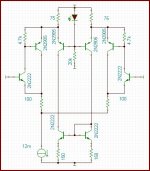
You can use a Sziklai output from a current mirror to provide gain, yes. You can see this used in the attached schematic (Q1/2/5 and Q3/4/6). This should work fine at an output of 100mA, although the input current will be less of course.forr said:...Do you think of of the input of the CM with a single transistor connected as a diode, as usual, mirrored by the controling transistor of the Sziklai pair, which then can provide current gain as you said ?..
Oh, well apparently the schematic is too big to attach, so I will link to it instead:
An externally hosted image should be here but it was not working when we last tested it.
forr said:Hi Eva,
I have thought of that before posting the question, buf it probably won't be as fast as a simple scheme and may introduce stability problems for what I have in mind.
But now we have 100Mhz video op-amps...
Re: Re: Re: Re: Re: High current mirror ?
No, I mean I am sick of personal attacks he starts as soon as sees some original idea.
syn08 said:
Do you really think JC and perhaps other guys in the industry are ripping off design ideas from this forum? I don't think so, but if God forbid this proves to be right, and if it would be worth of ( unlikely 🙂 ) I may decide to legally pull some eyes. Been there, done that. BTW, under the US law patenting is not really required to protect an idea. You can make a case in court if you keep track of your stuff.
No, I mean I am sick of personal attacks he starts as soon as sees some original idea.
Eva,
Using an op-amp will need a power supply and some more components. I would like to stay in a simple bipolar configuration.
Using an op-amp will need a power supply and some more components. I would like to stay in a simple bipolar configuration.
Thinking about this a bit more: When you say you want currents "up to" 100mA, do you need a mirror to cover the whole range 0-100mA, or closer to a fixed current? The Sziklai output mirror will be reasonably linear over a small range, but the proportion of current in each of the two transistors in the Sziklai pair changes with total output current, which effectively changes the gain. The change is significant if you try to use it over a wide range of currents, if you need it to be linear.
Yeah, I use that many LEDs partly just to look nice. They do all serve a practical purpose too though, I don't put things in only for show.Lumba Ogir said:Mr Evil,
fairy light bulbs to illuminate the Christmas tree?
You can get inspiration from the datasheet of MAT02 and MAT03. Check out a cascode current mirror. The main power dissipation will the cascode transistor handle and the current mirroring will the small signal transistor handle.
Hi Mr Evil,
---Thinking about this a bit more: When you say you want currents "up to" 100mA, do you need a mirror to cover the whole range 0-100mA, or closer to a fixed current?---
A variable range. I'll show the circuit I'am thinking of later, it already works quite well with a current mirror with 10 mA in each branch.
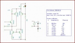
Here is a buffer inspired by P. L. Taylor amp as published in the Wireless World issue of June 1973. There is some relationship with the White cathode follower.
The only reference I found which exploited the idea was :
http://www.tubecad.com/2004/blog0023.htm
Here I use a Sziklai pair followed by a common base transistor in the so-called folded cascode configuration and then a current mirror the output of which is connected to the emitter of the input transistor.
Results of the simulation are good.
In the first real tests, at 4 V in 1 kOhm, distorsion at 0.0004% is near 10 times lower than a Sziklai follower loaded by a 6 mA CCS.
It may need some frequency compensation.
The subject of this thread was aimed to answer to the question : how much current can I use in the CM in this configuration before it degrades the performances ?
Comments wellcome.
Attachments
- Status
- Not open for further replies.
- Home
- Amplifiers
- Solid State
- High current mirror ?