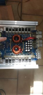
I got a Analog Amp, with damaged Output Channel.
Damaged are:
Toshiba 2SA1987-O
Toshiba 2SC 5359-O
K C4370A
K A1659A.
The question is now, i can order the Parts only at UTSource.
I dont know, if i can use other parts with same parameters.
How it will act, if i use other Transistor, with same parameters, and i use the amp later in Bridge mode?
Will this have any affect, if one channel has the original parts, and the other not?
Do anybody have another source for the parts?
If there are no pots, it's very likely a class B and they don't have a bias current. Unless it's drawing more current than it should, the bias is OK.
Since you used something other than the original output transistors, you should bench the amp until it thermals and confirm, at several points while it's heating up and cooling down, that the idle current has remained relatively unchanged.
Since you used something other than the original output transistors, you should bench the amp until it thermals and confirm, at several points while it's heating up and cooling down, that the idle current has remained relatively unchanged.
So, i think there is something more damaged.
If i connect a testload 2,8Ohm on one channel, i can go up with my power supply to 60 Amps, i get an Output Voltage from 22 Volt. Input is 12V an 100Hz Signal. The channel iam testing very quickly get very hot. Never mind which channel i test, both heat the same up. I dont know, if this is normal. The Signal all the time is good, but iam affraid to run it longer than one minute, because if i touch the heatsink, its allmost more than 45°C in 30 Seconds.
For Info: Only one channel was damaged. The owner leave the amp open, and a piece of metal fall inside and bridged the rail to the emiter resistor of the broken channel
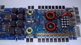
That's not normal. Push/pull/twist the transformers as well as pushing on various parts of the board with an insulated probe. Do you see any intermittent problems causing similar changes in current?
If not, while the amp is doing this, measure the DC voltage across the emitter resistors to see if you can see the voltage changing from 0.000v to something higher.
If not, while the amp is doing this, measure the DC voltage across the emitter resistors to see if you can see the voltage changing from 0.000v to something higher.
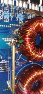
Maybe somebody have a diagram, how to connect the transformers? I disconnected one,
and forgot, how to connect the windings. The first transformer is standard, secondare center is ground. The one i have disconnected, has also windings for control voltage. But the problem is, that the center is not ground. I was irritated, when i took measurments. Ground on secondary center tap, the other tip on the recitifiers. Outside the recitifiers i measured 200V, in the middle of the rectifiers 0V. The other transformer i measured 700V,,,
and forgot, how to connect the windings. The first transformer is standard, secondare center is ground. The one i have disconnected, has also windings for control voltage. But the problem is, that the center is not ground. I was irritated, when i took measurments. Ground on secondary center tap, the other tip on the recitifiers. Outside the recitifiers i measured 200V, in the middle of the rectifiers 0V. The other transformer i measured 700V,,,
- Status
- This old topic is closed. If you want to reopen this topic, contact a moderator using the "Report Post" button.
- Home
- General Interest
- Car Audio
- Hifonics Colossus X3