Hello recieved this amp for repair, it powers up and does not draw any current and seems stable. It will produce audio for a few seconds then goes into protect.
I checked the output terminals for for DC and the amp starts at 0 vdc when first powered, the DC steadily rises to -3.578 vdc then the protect kicks in, then the DC slowly discharges back to 0 vdc.
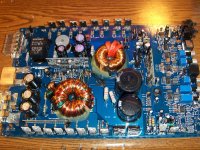
One of the rail caps was a little swollen but had not vented, they are 4700uf 63v and all I have is 4700uf 80v. I replaced the one as you will notice in the pics, should I replace the other to match or does it matter?
Could this be the transistors on the audio board marked 1d and 2d as the culprit?
pic1: the board
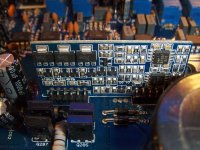
pic2: audio driver board
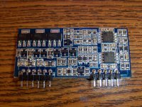
pic3: pwm board
I checked the output terminals for for DC and the amp starts at 0 vdc when first powered, the DC steadily rises to -3.578 vdc then the protect kicks in, then the DC slowly discharges back to 0 vdc.
One of the rail caps was a little swollen but had not vented, they are 4700uf 63v and all I have is 4700uf 80v. I replaced the one as you will notice in the pics, should I replace the other to match or does it matter?
Could this be the transistors on the audio board marked 1d and 2d as the culprit?
pic1: the board
pic2: audio driver board
pic3: pwm board
Attachments

I don't know how your supply works but none of mine will drop to that voltage unless they're loaded beyond their current rating.
Insert a low value current limiting resistor (2 ohm would be OK but a 1 ohm may be better) in the B+ line to see if it still draws the voltage down.
Insert a low value current limiting resistor (2 ohm would be OK but a 1 ohm may be better) in the B+ line to see if it still draws the voltage down.
I removed the new rail cap I installed and now the amp will power up? I think I put it in backwards by mistake. What a rookie move.
BRB
BRB
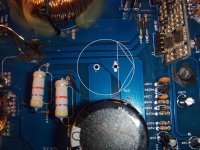
Look at the silkscreen. The negative terminal will be marked. According to the cap orientation in similar amps, it looks right in the photo.
I thought the grounds of the rail caps would be directly connected to each other. The only marking I see is a big arrow.
I hook power to the replacement cap out of the circuit and it charges and holds a charge.
If I install it in the same orientation as the other cap it wont power on.
Does the positive of one cap connect to the negative of the other?
I hook power to the replacement cap out of the circuit and it charges and holds a charge.
If I install it in the same orientation as the other cap it wont power on.
Does the positive of one cap connect to the negative of the other?
I've never seen one marked like that. The two caps would be directly connected by the secondary ground. One would have the positive terminal on the secondary ground. The other would have its negative on the secondary ground.
You should also be able to find direct connections between the positive rectifier and the positive terminal of one cap. The same from the negative rectifier to the negative terminal of the other cap.
You should also be able to find direct connections between the positive rectifier and the positive terminal of one cap. The same from the negative rectifier to the negative terminal of the other cap.
The negative is the triangle so one cap's negative is connected to the others positive.......hmmm
Amp powers up idles fine, same issue. The + output terminals have - voltage and soon as it reaches -3.5 vdc the protect kicks in and the voltage slowly discharges back down to almost zero but still reads negative.
When the amp is first powered up I have a nice square wave on all the gates of the p/s fets. When the voltage reaches -3.5 vdc on the output terminals and the protect kicks in I lose the square wave on the gates.
The protection is shutting the supply down. What would cause the slow rise of negative DC on the + output terminal and cause the supply to shutdown?
The protection is shutting the supply down. What would cause the slow rise of negative DC on the + output terminal and cause the supply to shutdown?
Check for broken legs on the outputs. If none are broken, I'd suggest replacing the TL072s on the driver board (top one first). You should be able to do it without removing the driver board.
As a side note...
When you removed the driver board, you should have been able to do it with only about 1/4-3/8 of an inch of ChipQuik. If you used significantly more, you should try a bit less next time.
I've been trying to get people to buy CQ for years and only a VERY few have done it. I see photos or driver board after driver board with pulled vias. I don't understand why they won't buy it.
I would expect the supply to shut down as soon as the DC reached the threshold set by the protection circuit. I don't know where that threshold is.
It's also possible that you have DC feeding the driver board from the preamp section.
It's also possible that you have DC feeding the driver board from the preamp section.
- Status
- Not open for further replies.
- Home
- General Interest
- Car Audio
- Hifonics Brutus BXi1208D