I'd suggest that you not use NTE parts. They may be OK here but that's definitely not the case, especially in class D circuits.
1 ohm to ground for the base seems wrong.
Pull all 4 driver transistors and re-post the resistance. Do NOT apply power.
1 ohm to ground for the base seems wrong.
Pull all 4 driver transistors and re-post the resistance. Do NOT apply power.
After pulling drivers, numbers remained the same. This is with pwba still removed, not fets and no drivers.
Should the lm393 have similar values on each side. I looked up the pinout and have foung that input resistance that is 10k less on pin 2 then pin 6.
At this point, what's out of the board?
A current photo (one taken after you read this post, nothing earlier) showing everything that's out of the amp would be helpful.
A current photo (one taken after you read this post, nothing earlier) showing everything that's out of the amp would be helpful.
I actually put the pwba back in and the drivers. I put a load resistor in as described before. I get 3.6 volts prior to the gate resistor, 3.52 volts after gate resistor when load is placed between gate and pad 3. I get 4.5 volts at gate if load is applied to gate and base. It is now the same for both sides. I get .05 amps with power applied (no fets) which goes to .1 when the relay kicks in.
On the side that shows a significant increase in the gate voltage when loaded gate to drain, follow the drive circuit back and compare the voltage on both sides on the following points. Copy and paste the list and fill in the blanks.
Emitter of PNP driver transistor
Bank 1
Bank 2
Base of PNP driver transistor
Bank 1
Bank 2
Collector of PNP driver transistor
Bank 1
Bank 2
Pin 9 of driver IC (494 or equivalent)
?
Pin 10 of driver IC (494 or equivalent)
?
Emitter of PNP driver transistor
Bank 1
Bank 2
Base of PNP driver transistor
Bank 1
Bank 2
Collector of PNP driver transistor
Bank 1
Bank 2
Pin 9 of driver IC (494 or equivalent)
?
Pin 10 of driver IC (494 or equivalent)
?
Emitter of PNP driver transistor
Bank 1 3.376
Bank 2 3.378
Base of PNP driver transistor
Bank 1 4.020
Bank 2 4.018
Collector of PNP driver transistor
Bank 1 .003
Bank 2 .003
Pin 9 of driver IC (494 or equivalent)
? 4.654
Pin 10 of driver IC (494 or equivalent)
? 4.655
This was done with out load. Values are different under load. Both banks see identical voltages under load, approximately 1 volt higher when load is placed on base and drain versus when connected to base and source.
Yes, when placing a 1k resistor between gate and drain, aI see 1 volt higher then when 1k resistor is placed between gate and source; however? Both banks now show near identical numbers when tested in similar configurations. I did try reinstalling power fets. I clamped them down and applied power. When remote was connected, the amperage draw went to 7.8 amps before my power supply shut down in protect (it is capable of supporting 90 amps). When I tried to reapply power, I could not turn on power supply as it seems a fet went to dead short. I pulled the power fets back out. The amp will accept power now (just powered up to get values for you as requested); however, a dmm check of the fets shows no short. Could the rectifiers be bad or should I look else where.
Pulling the rectifiers would further isolate the power supply from the audio stage.
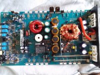
In the photo, there are two missing gate resistors. Have you installed them?
What happened to cause the two halves to now match when they were significantly different before?
In the photo, there are two missing gate resistors. Have you installed them?
What happened to cause the two halves to now match when they were significantly different before?
The board in this amp has locations to add 1 more power fet and gate resistor to each bank as well as 1 more output and 1 more output to each bank. I beleive this is the same board as used in the 1500.1d but with less components. I was wandering if adding them would make any changes after the amp was repaired, but asumed that the amp would not support the additional power with out further upgrades. As for the equalization of the banks, I replaced the lm494 and lm393. I don't know if that helped or not. Does it sound as if the power section may be correct and that the issue is in the output section. The output fets did not show as shorted with a dmm. Why would the power fets create a dead short in the power section if the fets do not read as shorted on a dmm? I just want to say thanks for your help.
I pulled the rectifiers, put in the power fets and 1 immediately shorted out. What do you mean by transformer? Are you speakuing about the toroid?
Toroid is a shape.
The transformer is the toroidal core wrapped with wire.
Did you have the FETs clamped?
You may have an intermittent connection in the drive circuit. It would have been much better to troubleshoot to the fault than to blindly replace parts.
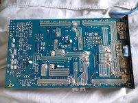
Did you clean the solder pads on the rectifiers to be sure that there were no solder bridges.
The transformer is the toroidal core wrapped with wire.
Did you have the FETs clamped?
You may have an intermittent connection in the drive circuit. It would have been much better to troubleshoot to the fault than to blindly replace parts.
Did you clean the solder pads on the rectifiers to be sure that there were no solder bridges.
Yes the fets were clamped. I cleaned the pads and could see no solder bridges. I have checked soldering connections and touched up any solder joints that appeared to look bad. I can't think of what else to check.
Do you have a current limiting resistor?
Does your 12v power supply simply shut down at the current set-point or does it remain on with a drop in output voltage?
Does your 12v power supply simply shut down at the current set-point or does it remain on with a drop in output voltage?
- Status
- Not open for further replies.
- Home
- General Interest
- Car Audio
- Hifonics bre110.1d