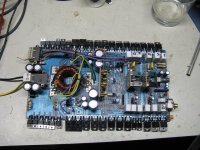
Hi, i have recently aquired an old hifonics boltar that has a problem with drawing current only when power is applied to the remote terminal, changed out all 10 IRFZ44N mosfets in the power supply, also checked all of the 220ohm gate resistors all were within tolerance, also all output devices and drivers checked good, attached is a picture of the amplifier only the power supply fets on towards the top of the picture get warm the others are cool, amp did the same thing before i changed all the fets in the power supply i have more pics of scope readings and power supply pics of when amp is on
Attachments
Can you post photos of the gate signal (on the gate leg of the FET) for each bank of FETs (1 photo/bank)?
If possible, also post photos of the drive signals on the base of the driver transistors.
If possible, also post photos of the drive signals on the base of the driver transistors.
If the Boltar is equipped with SGSD100 and SGSD200 check them with an ohmmeter. I once worked on a VIII - Zeus and the SGSD200 had failed. The SGS are part of the power supply. If they have a short you might have trouble finding the SGSD. The company audiodesign (distributor in Germany) fixes the Series VIII amplifiers with "self made" SGSD100 / 200. transistors. They make their own darlingtons with TIP102+TIP35C (replaces SGSD100), TIP107+TIP36C (replaces SGSD200).
If there was no other source , you can get the SGSD100 here
http://bg-electronics.de
and the SGSD200 here:
www.conrad.com
You may also check the output sinal of the TL594 , as in a Pluto repair the TL594 had gone bad and didn´t provide both output signals. the TL594 is located on the small sub-board next to the transformer.
Pull the driver transistor (2SD1292?) and check it. If it's OK, the output transistor of the TL594 may have failed. Check the drive signal on pins 9 and 10 of the 594 with the driver transistor out of the circuit. It should look more like the drive signal you have on the bottom bank of FETs.
If you pull both driver transistors, the voltage drop through your 4 ohm resistor should be much less and should allow the drive signal to swing to ~12v. The low voltage (caused by the 4 ohm resistor) could be causing the driver IC to go into shutdown. If you have two 4 ohm resistors, connect them in parallel to allow more voltage at the amp.
If you pull both driver transistors, the voltage drop through your 4 ohm resistor should be much less and should allow the drive signal to swing to ~12v. The low voltage (caused by the 4 ohm resistor) could be causing the driver IC to go into shutdown. If you have two 4 ohm resistors, connect them in parallel to allow more voltage at the amp.
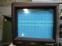
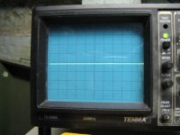
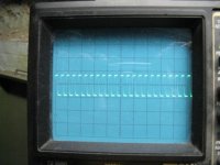
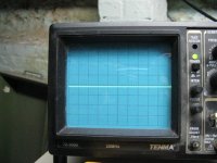
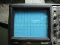
sorry i do not have another 4 ohm resistor this is the only one i have with resistor in series and drivers out of circuit with remote attached i get on both pins 9 and 10 of the 594 IC i get indentical square waves 3 volts on the plus side and 2 volts on the minus side of center 5 volts peak to peak id say both drivers checked good and the drivers are 2sc2061 transistors, also i get the same square wave at both bases where the drivers were
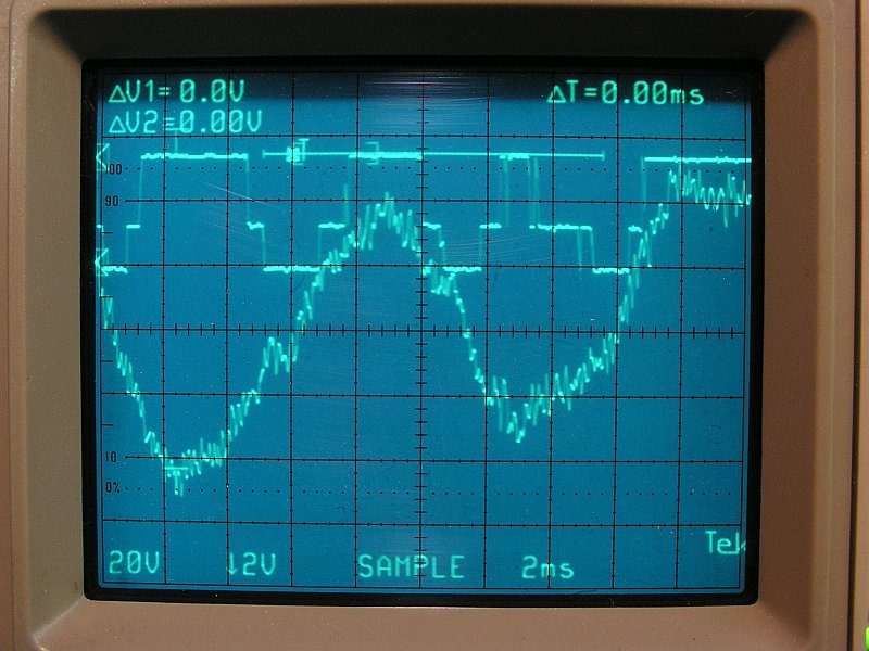
ive found something very interesting with only the driver in the bottom bank installed the amp powers up as is should i tried that same driver in the other side and it does not power up, also ive found a 3 ohm resistor to put in parallel with the 4 ohm seems to be working with that, when powered up with only the bottom bank driver in place all rail voltages are there and when its powered up the square wave becomes a jagged wave.
Do all of the upper bank FETs get hot?
If not, measure the resistance from one gate leg to the next. They should read 2x the value of the individual gate resistors. This will confirm that there are no broken connections between the transistors and the gate resistors.
Is the 47 ohm pulldown resistor within tolerance?
If not, measure the resistance from one gate leg to the next. They should read 2x the value of the individual gate resistors. This will confirm that there are no broken connections between the transistors and the gate resistors.
Is the 47 ohm pulldown resistor within tolerance?
yes all of them get hot and from leg to leg on all 5 i get about 440 ohms which is about double 220 which are the value of the gate resistors. and the pull down resistor is 47.12 ohms
Although I don't think this problem is caused by the gate resistors, their value may be slightly too high for the FETs to switch efficiently.
Try measuring the voltage (AC and DC) across each of the gate resistors in both banks. Are they all approximately the same?
Is the connection from the 47 ohm resistor to ground OK?
Is the connection from the 47 ohm resistor to the gate resistors OK?
Try measuring the voltage (AC and DC) across each of the gate resistors in both banks. Are they all approximately the same?
Is the connection from the 47 ohm resistor to ground OK?
Is the connection from the 47 ohm resistor to the gate resistors OK?
ok, ive found the problem ive discovered that the 47 ohm pull down resistor was not connected to the gates, so i put a jumper wire from the side of the 47 ohm resistor that is not grounded to the gates and it powered up, i cannot find a trace on the board where it is or was connected to the gate resistors
This amp probably has a regulated supply so, under normal operating conditions, the pulse width will be well below the maximum duty cycle. To determine if the 220 ohm resistors will cause problems, lower the DC supply voltage to approximately 10.5v. If the idle current is higher at 10.5 v than at 13v, the gate resistors need to be replaced.
Do this with a 10 amp fuse in the B+ line (no resistor) and have the transistors tightly clamped to the sink.
Do this with a 10 amp fuse in the B+ line (no resistor) and have the transistors tightly clamped to the sink.
i will do that tommorrow perry as of right now it appears to function correctly, if i have any other problems i will post,
thanks alot perry i really appreicate it
thanks alot perry i really appreicate it
It does not look like an amplifier with regulated supply, it looks like a class G or class H amplifier with two or three  sets of supply rails. It's the first time I see something like that in car audio.
sets of supply rails. It's the first time I see something like that in car audio.There were quite a few amps that had multiple rails. Earthquake, Hifonics... Carver had one also.
The following photo is from an Earthquake amp. This one has 3 rails. I think the Carver had only 2 rails.
Vypr can check to see if the duty cycle changes when he varies the voltage from 10.5v to 13v.
The following photo is from an Earthquake amp. This one has 3 rails. I think the Carver had only 2 rails.
Vypr can check to see if the duty cycle changes when he varies the voltage from 10.5v to 13v.
- Status
- Not open for further replies.
- Home
- General Interest
- Car Audio
- Hifonics Boltar VIII Problem