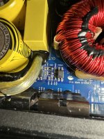
Do you read any voltage on the input side when the amp would normally go into protect?
Is it shorted across the output terminals?
Is it shorted across the output terminals?
With the amp powered up (R624 & D606 removed), there is no voltage on the input side (assuming this is the side facing away from the output FETs). Measuring the output side (facing the FETs), I get -74V with my probe referenced to power ground.
Resistance across the output side reads ~11.8kOhms. Resistance across the input side reads ~4 ohms.
Resistance across the output side reads ~11.8kOhms. Resistance across the input side reads ~4 ohms.
Weird, I removed the opto and the output side is measuring ~22kOhms. Input side is >9Megs.
Measuring the pads on the board where the opto sits, output side is measuring “open”, input side is measuring ~11.8kOhms.
Measuring the pads on the board where the opto sits, output side is measuring “open”, input side is measuring ~11.8kOhms.
Solder the resistor and diode back in and make sure the amp works.
Could there have been a wire strand on the board?
Measure the voltage across the input pads when the amp would have been in protect. Is it 0v?
Could there have been a wire strand on the board?
Measure the voltage across the input pads when the amp would have been in protect. Is it 0v?
I put back R624 and D606 along with the opto and now the amp powers up fine. I did not see any strands of wire when I removed it. Could the opto be faulty and when I heated it up during removal it “fixed” it?
I don't know what happened. At least you have the general area of the fault. I'd try heating and cooling (freezing spray) that opto and the other two in the area to see if any faults show up.
That’s true, it seems to have been caused by the opto at this point. I just tried spraying cold spray and it didn’t affect it or the one next to it.
What is this opto for? Is there a part number for it?
What is this opto for? Is there a part number for it?
PC817C. It's nothing special.
OP602 combines the output of the optocouplers 603/604 and the two transistors... all of which work for the over-current sensing circuit across the shunt resistors. I don't know if your circuit is identical but it's likely similar.
OP602 combines the output of the optocouplers 603/604 and the two transistors... all of which work for the over-current sensing circuit across the shunt resistors. I don't know if your circuit is identical but it's likely similar.
Thank you, Perry. 🙂
I'll run it through some tests and keep an eye on it. If it fails again I'll try replacing the opto.
I'll run it through some tests and keep an eye on it. If it fails again I'll try replacing the opto.
- Home
- General Interest
- Car Audio
- Hifonics A3000.1D
